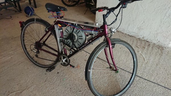
Gutted Hoverboard Becomes Formidable Track-Drive Robot

When “hoverboards” first came out, you may have been as disappointed as we were that they did not even remotely fulfill the promises of Back to the Future II. Nothing more than a fancified skateboard, hoverboards are not exactly groundbreaking technology. That doesn’t mean they’re not useful platforms for hacking, though, as this hoverboard to track-propelled robot tank conversion proves.

Most of the BOM for this build came from the junk bin – aluminum extrusions, brackets, and even parts cannibalized from a 3D-printer. But as [pasoftdev] points out, the new-in-box hoverboard was the real treasure trove of components. The motors, the control and driver electronics, and the big, beefy battery were all harvested and mounted to the frame. To turn the wheels into tracks, [pasoftdev] printed some sprockets to fit around the original tires. The tracks were printed in sections and screwed to the wheels. Idlers were printed in sections too, using central hubs and a clever method for connecting everything together into a sturdy wheel. Printed tank tread links finished the rolling gear eventually; each of the 34 pieces took almost five hours to print. The dedication paid off, though, as the 15-kg tank is pretty powerful; the brief video below shows it towing an office chair around without any problems.

We noticed that [pasoftdev] found the assembly of the tread links a bit problematic. These 3D-printed links that are joined by Airsoft BBs might make things a little easier next time.

Continue reading “Gutted Hoverboard Becomes Formidable Track-Drive Robot”

Jigsaw Motor Uses PCB Coils For Radial Flux

Electric motors are easy to make; remember those experiments with wire-wrapped nails? But what’s easy to make is often hard to engineer, and making a motor that’s small, light, and powerful can be difficult. [Carl Bugeja] however is not one to back down from a challenge, and his tiny “jigsaw” PCB motor is the latest result of his motor-building experiments.

We’re used to seeing brushless PCB motors from [Carl], but mainly of the axial-flux variety, wherein the stator coils are arranged so their magnetic lines of force are parallel to the motor’s shaft – his tiny PCB motors are a great example of this geometry. While those can be completely printed, they’re far from optimal. So, [Carl] started looking at ways to make a radial-flux PCB motor. His design has six six-layer PCB coils soldered perpendicular to a hexagonal end plate. The end plate has traces to connect the coils in a star configuration, and together with a matching top plate, they provide support for tiny bearings. The rotor meanwhile is a 3D-printed cube with press-fit neodymium magnets. Check out the build in the video below.

Connected to an ESC, the motor works decently, but not spectacularly. [Carl] admits that more tweaking is in order, and we have little doubt he’ll keep optimizing the design. We like the look of this, and we’re keen to see it improved.

Continue reading “Jigsaw Motor Uses PCB Coils For Radial Flux”

An Open Source ESC For Brushless Motors

For something basic like a brushed DC motor, speed control can be quite simple, and powering up the motor is a simple matter of just applying voltage. Brushless motors are much more demanding in their requirements however, and won’t spin unless driven just right. [Electronoobs] has been exploring the design of a brushless speed controller, and just released version 1.0 of his open-source ESC design.

The basic design is compact, and very similar to many off-the-shelf brushless ESCs in the low power range. There’s a small PCB packing a bank of MOSFETs to handle switching power to the coils of the motor, and a big capacitor to help deal with current spikes. The hacker staple ATMEGA328 is the microcontroller running the show. It’s a sensorless design, which measures the back EMF of the motor in order to determine when to fire the MOSFETs. This keeps things simple for low-torque, low-power applications.

It’s a tidy build, and the latest revision shows a lot of polish compared to the earlier prototypes. If you’re interested to learn more, try building it yourself, or consider building a thrust testing rig for your bench at home. Video after the break.

Continue reading “An Open Source ESC For Brushless Motors”

A Pet Robot, Just Like Boston Dynamics Makes

Every few months or so, a new video from Boston Dynamics will make the rounds on the Internet. This is their advertising, because unless the military starts buying mechanical mules, Boston Dynamics is going to be out of business pretty soon. You’ll see robots being kicked down the stairs, robots walking through doors, and robots acting like dogs. If a hundred or so highly skilled and highly educated roboticists, technologists, and other experts can put together a walking dog robot in a decade, obviously one person can cut through the cruft and build one in a basement. That’s what [Misha] is doing. It’s the Dizzy Wolf, a robotic wolf, or dog, or cat, we don’t actually know because there’s no fur (or head) yet. But it is interesting.

The key component for any quadruped robot is a high-torque, low-noise servo motor. This isn’t a regular ‘ol brushless motor, and for this application nine gram servos go in the trash. This means custom made motors, or DizzyMotors. You’re looking at a big brushless motor with a planetary gearset, all squished into something that could actually fit into the joint of a robotic wolf’s leg.

There’s a driver for these motors, strangely not called the DizzyDriver, that turns a BLDC into a direct drive servo motor. It is effectively a smart servo, that will move to a specific rotation, receive commands over RS-485, and write back the angular position. It also applies constant torque. Of course, there is a video of the DizzyMotor and servo driver below.

Building a robotic dog that will walk around the house is one of the hardest engineering challenges out there. You’ve got fairly crazy kinematics, you’ll need to think about the strength of the frame, control systems, and eventually how to fit everything in a compact design. This project is hitting all the marks, and we can’t wait to see the Dizzy Wolf do a backflip or chase a ball.

Continue reading “A Pet Robot, Just Like Boston Dynamics Makes”

Retired Rideshare Scooter Skips The Reverse Engineering To Ride Again

[Adam Zeloof] (legally) obtained a retired electric scooter and documented how it worked and how he got it working again. The scooter had a past life as a pay-to-ride electric vehicle and “$1 TO START” is still visible on the grip tape. It could be paid for and unlocked with a smartphone app, but [Adam] wasn’t interested in doing that just to ride his new scooter.

His report includes lots of teardown photos, as well as a rundown of how the whole thing works. Most of the important parts are in the steering column and handlebars. These house the battery, electronic speed controller (ESC), and charging circuitry. The green box attached to the front houses a board that [Adam] determined runs Android and is responsible for network connectivity over the cellular network.

To get the scooter running again, [Adam] and his brother [Sam] considered reverse-engineering the communications between the network box and the scooter’s controller, but in the end opted to simply replace the necessary parts with ones under their direct control. One ESC, charger, and cheap battery monitor later the scooter had all it needed to ride again. With parts for a wide variety of electric scooters readily available online, there was really no need to reverse-engineer anything.

Ridesharing scooter startups are busy working out engineering and security questions like how best to turn electric scooters into a) IoT-connected devices, and b) a viable business plan. Hardware gets revised, and as [Adam] shows, retired units can be pressed into private service with just a little work.

The motors in these things are housed within the wheels, and have frankly outstanding price-to-torque ratios. We’ve seen them mated to open-source controllers and explored for use in robotics.

Teardown Shows Why Innovative Designs Sometimes Fail

Some ideas are real head-scratchers from a design standpoint: Why in the world would you do it that way? For many of us, answering that question often requires a teardown, which is what [Ben Katz] did when this PCB motor-powered weed whacker came across his bench. The results are instructive on what it takes to succeed in the marketplace, or in this case, how to fail.

The unit in question comes from an outfit called CORE Outdoor Power. The line trimmer was powered by a big lithium-ion battery pack, but [Ben] concentrated on the unique motor for his teardown. After a problematic entry into the very sturdy case at the far end of the trimmer’s shaft, he found what looks like a souped-up version of [Carl Bugeja]’s PCB brushless motors. The rotors, each with eight large magnets embedded, are sandwiched on either side of a very thick four-layer PCB with intricately etched heavy copper traces. The PCB forms the stator, with four flat coils. The designer pulled a neat trick with the Hall-effect sensors needed for feedback; rather than go with surface-mount sensors, which would add to the thickness of the board, they used through-hole packages soldered to surface pads, with the body of the sensor nestled in a hole in the board. The whole design is very innovative, but sadly, [Ben]’s analysis shows that it has poor performance for its size and weight.

Google around a bit and you’ll see that CORE was purchased some years back by MTD, a big player in the internal combustion engine outdoor power market. They don’t appear to be a going concern anymore, and it looks as though [Ben] has discovered why.

[Jozef] tipped us off to this one. Thanks!

Can You 3D-Print A Stator For A Brushless DC Motor?

Betteridge’s Law holds that any headline that ends in a question mark can be answered with a “No.” We’re not sure that [Mr. Betteridge] was exactly correct, though, since 3D-printed stators can work successfully for BLDC motors, for certain values of success.

It’s not that [GreatScott!] isn’t aware that 3D-printed motors are a thing; after all, the video below mentions the giant Halbach array motor we featured some time ago. But part of advancing the state of the art is to replicate someone else’s results, so that’s essentially what [Scott!] attempted to do here. It also builds on his recent experiments with rewinding commercial BLDCs to turn them into generators. His first step is to recreate the stator of his motor as a printable part. It’s easy enough to recreate the stator’s shape, and even to print it using Proto-pasta iron-infused PLA filament. But that doesn’t come close to replicating the magnetic properties of a proper stator laminated from stamped iron pieces. Motors using the printed stators worked, but they were very low torque, refusing to turn with even minimal loading. There were thermal issues, too, which might have been mitigated by a fan.

So not a stunning success, but still an interesting experiment. And seeing the layers in the printed stators gives us an idea: perhaps a dual-extruder printer could alternate between plain PLA and the magnetic stuff, in an attempt to replicate the laminations of a standard stator. This might help limit eddy currents and manage heating a bit better. Continue reading “Can You 3D-Print A Stator For A Brushless DC Motor?”