Supercapacitors are definitely not the same as batteries, we all know that. They tend to have a very low operating voltage, and due to their operating principle of storing charge on parallel plates, their discharge curve is quite unfriendly for modern microcontroller devices. Energy storage efficiency per unit volume is also low compared with modern lithium polymer (LiPo) batteries so all in all they don’t look all that useful for many of our projects. However, as [Andreas Spiess’] latest video demonstrates, they do have some redeeming features that might make them useful for certain embedded applications.
The low operating voltage initially looks like an issue for devices operating at a typical 3.3V, and it’s tempting to simply wire a few in series and roll with it. But as [Andreas] explains in his typically clear manner, it would be necessary to have a complex power stage, operating in buck mode with capacitor voltage above the required level, and in boost mode when it heads below. Too complex – it’s much easier to simply stick with a low voltage bank of paralleled supercaps, and just operate always in boost mode. Even doing this, you’re not realistically going to get more than a handful of hours operating voltage with an always active device.
So why bother at all with supercaps, surely using a LiPo is so much easier and better? In many cases the answer is definitely a yes. But LiPo cells must not be charged in freezing temperatures (apart from certain special low temp products), else the cell can rapidly be destroyed due to lithium metal deposition at the anode. Also you need to be careful charging them, especially when they’re heavily discharged, as they are easily damaged without the proper treatment. LiPo cells operate based on chemical principles – lithium ions literally have to move around inside the structure, and eventually the battery will wear out.
Supercapacitors have the advantage of very long life (but sometimes, they do leak) much more aggressive charging and discharging behaviours and will operate down to very low temperatures. This makes them very useful when a large amount of power is available sporadically (for super fast charge cycles) or in places where temperatures stay persistently very low, such as up a mountain were solar will work, albeit slowly, but LiPo batteries will definitely not be suitable.
Other battery chemistries are available, such as Lithium Iron Phosphate which can tolerate the cold. Also you can always just insulate the battery with an integrated heater and preheat the battery to a safe charging temperature as well. So, just like everything with electronics, it’s important to choose the correct parts for your application, and it all starts with the power source. Supercapacitors might just hit an appropriate price/performance point for that special application you had in mind.
Supercapacitors aren’t really suitable for many applications, like powering an eBike or running your laptop, but hey, they did it anyway.


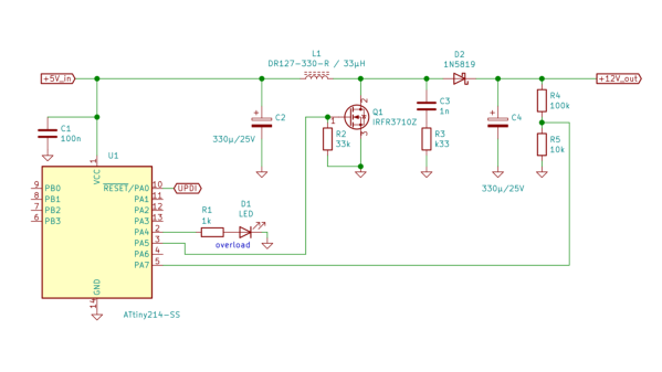
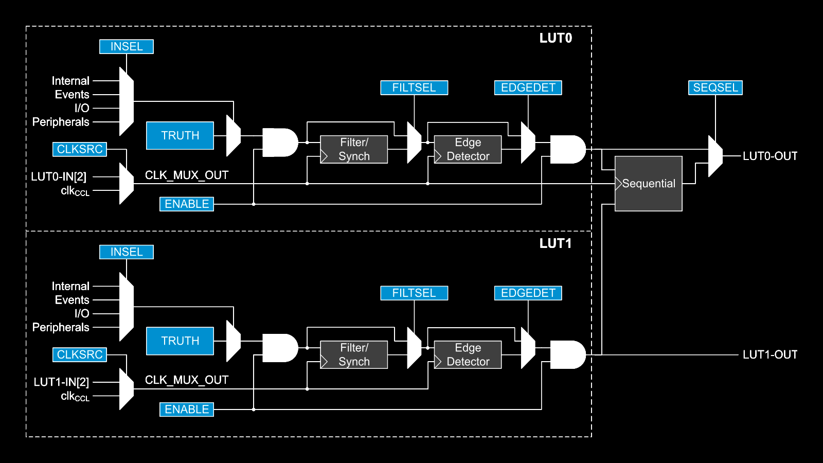
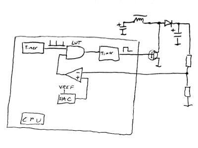 This napkinCAD sketch shows how [SM6VFZ] implemented the boost regulator in the ATtiny214. The AND gate is formed using one of the CCL LUT’s. The first “timer 1” on the left, connected to one input of the AND gate, is free running and set at 33 kHz. The analog comparator compares the boosted output voltage against an internally generated reference voltage derived from the DAC. The output of the comparator then “gates” timer 1 signal to trigger the second “timer 2” — which is a mono-shot timer set to max out at 15 us. This makes sure there is enough time left for the inductor to completely release its energy before the next cycle starts. You can check out the code that [SM6VFZ] used to built this prototype, and his generous amounts of commenting makes it easy to figure out how it works.