USB-C For Hackers: Reusing Cables

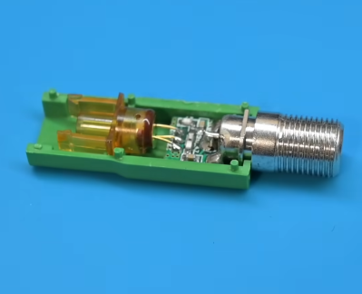
Your project needs a cable, and since USB-C cables are omnipresent now, it’s only natural to want to reuse them for your evil schemes. Ever seen USB 3.0 cables used for PCIe link carrying duty? It’s because USB 3.0 cables are built to a reasonably high standard, both sockets and cables are easy to find, and they’re cheap. Well, USB-C cables beat USB 3.0 cables by all possible metrics.

Let’s go through USB-C cable reuse in great detail, and see just what exactly you get when you buy either a gas station C-C USB 2.0 cable, or, the fanciest all-features-supported 240 W Thunderbolt cable that money can buy. Looking for a cable to cut, or something to pass a seriously high-speed link? You’re reading the right article.

The Omnipresent Cables

USB-A to USB-C cables are the least interesting. They’re equivalent to a microUSB to USB-A cable, except there’s a resistor on the USB-C plug, connected from VBUS to one of the CC pins. That’s it. The cable contains four conductors, there’s really not much new. Save these cables for all the devices still built without the 5.1 kΩ resistors.

Now, a USB-C to USB-C cable – let’s say, 60 W max, the default USB-C cable capability. If your cable says anything less than 60 W, say, “2 A” or “15 W”, that’s a lie – it can handle 60 W no problem, all USB-C to C cables can do 60 W. This cable is also cool – for one, it has five conductors; GND, VBUS, D+, D-, and CC. Two of them (GND and VBUS) are guaranteed to be thick enough to carry 3 A without much voltage drop if any, too!

Continue reading “USB-C For Hackers: Reusing Cables”

Pulley System Makes Headphone Cables More Managable

It’s 2024. You’ve probably got one or more pairs of wireless headphones around the house. [Barnso] prefers wired headphones with a long cable, but he also decries the fact that it often gets tangled in his chair. The solution? A pulley system to make everything easier.

The concept is simple. [Barnso]’s system uses three pulleys. The headphone cable goes to the PC, and then runs over the first pulley. It then runs under a second pulley which is free to move, but weighted so that it naturally wants to fall down under gravity. The cable then comes back up over a third pulley, and then runs to the headphones on [Barnso]’s head. Basically, it’s a super simple cable retraction mechanism that keeps the long headphone cable organized and in one place.

It’s nice to see a simple mechanism that makes life easier, particularly one that solves a problem so many of us have faced in real life. The construction shown in the video is almost (intentionally?) maddeningly hacky but it does the job. If you prefer to go wireless, though, we can show you how to do that too.

Continue reading “Pulley System Makes Headphone Cables More Managable”

Adapter Salad: Making Your Own Server Cables Because HP Won’t Sell Them To You

The world is tough and uncaring sometimes, especially if you’re at home tinkering with HP Enterprise equipment. If you’re in the same boat as [Neel Chauhan], you might have found that HPE is less than interested in interacting with small individual customers. Thus, when a cable was needed, [Neel] was out of luck. The simple solution was to assemble a substitute one instead!

[Neel] had a HPE ProLiant ML110 Gen11 server, which was to be used as network-attached storage (NAS). Unfortunately, it was bought as an open box, and lacked an appropriate serial-attached SCSI (SAS) cable. Sadly, HPE support was of no assistance in sourcing one.

SlimSAS LP x8 to dual MiniSAS x4 cables aren’t easy to find from anyone else, it turns out. Thus, [Neel] turned to Amazon for help sourcing a combination of parts to make this work. A SlimSAS LP 8X to 2x MiniSAS SFF-8643 cable was used, along with a pair of Mini SAS SFF-8087 to SAS HD SFF-8643 female adapters. From there, SFF-8087 cables could be used to hook up to the actual SAS devices required. The total cost? $102.15.

The stack of cables and adapters looks a bit silly, but it works—and it got [Neel]’s NAS up and running. It’s frustrating when you have to go to such lengths, but it’s not the first time we’ve seen hackers have to recreate obscure cables or connectors from scratch! What’s the craziest adapter salad you’ve ever made?

Undersea Cable Repair

The bottom of the sea is a mysterious and inaccessible place, and anything unfortunate enough to slip beneath the waves and into the briny depths might as well be on the Moon. But the bottom of the sea really isn’t all that far away. The average depth of the ocean is only about 3,600 meters, and even at its deepest, the bottom is only about 10 kilometers away, a distance almost anyone could walk in a couple of hours.

Of course, the problem is that the walk would be straight down into one of the most inhospitable environments our planet has to offer. Despite its harshness, that environment is home to hundreds of undersea cables, all of which are subject to wear and tear through accidents and natural causes. Fixing broken undersea cables quickly and efficiently is a highly specialized field, one that takes a lot of interesting engineering and some clever hacks to pull off.

Continue reading “Undersea Cable Repair”

Ancient Cable Modem Reveals Its RF Secrets

Most reverse engineering projects we see around here have some sort of practical endpoint in mind. Usually, but not always. Reverse-engineering a 40-year-old cable modem probably serves no practical end, except for the simple pleasure of understanding how 1980s tech worked.

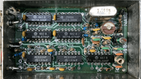
You’ll be forgiven if the NABU Network, the source of the modem [Jared Boone] tears into, sounds unfamiliar; it only existed from 1982 to 1985 and primarily operated in Ottawa, Canada. It’s pretty interesting though, especially the Z80-based computer that was part of the package. The modem itself is a boxy affair bearing all the hallmarks of 1980s tech. [Jared]’s inspection revealed a power supply with a big transformer, a main logic board, and a mysterious shielded section with all the RF circuits, which is the focus of the video below.

Using a signal generator, a spectrum analyzer, and an oscilloscope, not to mention the PCB silkscreen and component markings, [Jared] built a block diagram of the circuit and determined the important frequencies for things like the local oscillator. He worked through the RF section, discovering what each compartment does, with the most interesting one probably being the quadrature demodulator. But things took a decidedly digital twist in the last compartment, where the modulated RF is turned into digital data with a couple of 7400-series chips, some comparators, and a crystal oscillator.

This tour of 80s tech and the methods [Jared] used to figure out what’s going on in this box were pretty impressive. There’s more to come on this project, including recreating the original signal with SDRs. In the mean time, if this put you in the mood for other videotext systems of the 80s, you might enjoy this Minitel terminal teardown.

Continue reading “Ancient Cable Modem Reveals Its RF Secrets”

Get Today’s Forecast In Classic 90s Weather Channel Style

Remember when The Weather Channel actually had weather? It’s been a while, but we sure remember what a boon Local on the 8’s was when getting ready for the day. Not having to wait for the low-information national forecast on the morning shows or putting up with the antics of [Willard Scott] or [Al Roker] was just icing on the cake.

Recreating the retro look and feel of the Weather Channel experience is what this 1990s-style weather feed is all about, and we have to say that [Mitchell Scott] knocked it out of the park. Luckily, a lot of the heavy lifting was done already thanks to the WeatherStar 4000+ emulator project, which renders forecasts using online weather APIs in the distinctive retro graphics The Weather Channel used back in the day. He combined the graphics with the original smooth jazz soundtracks that TWC used back then; they’re online, because of course they are.

To really sell the look, [Mitchell] tracked down a period-correct Zenith TV with a 9″ CRT to display the feed from a Raspberry Pi 4’s composite video output. Why such a small screen? Easy. [Mitchell] wanted it on a shelf behind him to be visible during videoconferences. It’s a bit of a weird flex, but we respect it. Getting the composite video output working was a bit of a chore, as was tricking the TV into starting up on channel 14 so the feed is instantly visible.

The nostalgia is strong with this one, especially for weather geeks. For a more in-depth look at how The Weather Channel brought those local forecasts to cable, make sure you check out how the WeatherStar box was reverse-engineered.

Thanks to [USA-RedDragon] for the tip.

Blame It On The Sockets: Forensic Analysis Of The Arecibo Collapse

Nearly three years after the rapid unplanned disassembly of the Arecibo radio telescope, we finally have a culprit in the collapse: bad sockets.

In case you somehow missed it, back in 2020 we started getting ominous reports that the cables supporting the 900-ton instrument platform above the 300-meter primary reflector of what was at the time the world’s largest radio telescope were slowly coming undone. From the first sign of problems in August, when the first broken cable smashed a hole in the reflector, to the failure of a second cable in November, it surely seemed like Arecibo’s days were numbered, and that it would fall victim to all the other bad luck we seemed to be rapidly accruing in that fateful year. The inevitable finally happened on December 1, when over-stressed cables on support tower four finally gave way, sending the platform on a graceful swing into the side of the natural depression that cradled the reflector, damaging the telescope beyond all hope of repair.

The long run-up to the telescope’s final act had a silver lining in that it provided engineers and scientists with a chance to carefully observe the failure in real-time. So there was no real mystery as to what happened, at least from a big-picture perspective. But one always wants to know the fine-scale details of such failures, a task which fell to forensic investigation firm Thornton Tomasetti. They enlisted the help of the Columbia University Strength of Materials lab, which sent pieces of the failed cable to the Oak Ridge National Laboratory’s High Flux Isotope reactor for neutron imaging, which is like an X-ray study but uses streams of neutrons that interact with the material’s nuclei rather than their electrons.

The full report (PDF) reveals five proximate causes for the collapse, chief of which is “[T]he manual and inconsistent splay of the wires during cable socketing,” which we take to mean that the individual strands of the cables were not spread out correctly before the molten zinc “spelter socket” was molded around them. The resulting shear stress caused the zinc to slowly flow around the cable strands, letting them slip out of the surrounding steel socket and — well, you can watch the rest below for yourself.

As is usually the case with such failures, there are multiple causes, all of which are covered in the 300+ page report. But being able to pin the bulk of the failure on a single, easily understood — and easily addressed — defect is comforting, in a way. It’s cold comfort to astronomers and Arecibo staff, perhaps, but at least it’s a lesson that might prevent future failures of cable-supported structures.

Continue reading “Blame It On The Sockets: Forensic Analysis Of The Arecibo Collapse”