[Dennis] of [Made by Dennis] has been building a Voron 0 for fun and education, and since this apparently wasn’t enough of a challenge, decided to add a number of scratch-built improvements and modifications along the way. In his latest video on the journey, he rigorously calibrated the printer’s motion system, including translation distances, the perpendicularity of the axes, and the bed’s position. The goal was to get better than 100-micrometer precision over a 100 mm range, and reaching this required detours into computer vision, clock synchronization, and linear algebra.
To correct for non-perpendicular or distorted axes, [Dennis] calculated a position correction matrix using a camera mounted to the toolhead and a ChArUco board on the print bed. Image recognition software can easily detect the corners of the ChArUco board tiles and identify their positions, and if the camera’s focal length is known, some simple trigonometry gives the camera’s position. By taking pictures at many different points, [Dennis] could calculate a correction matrix which maps the printhead’s reported position to its actual position.
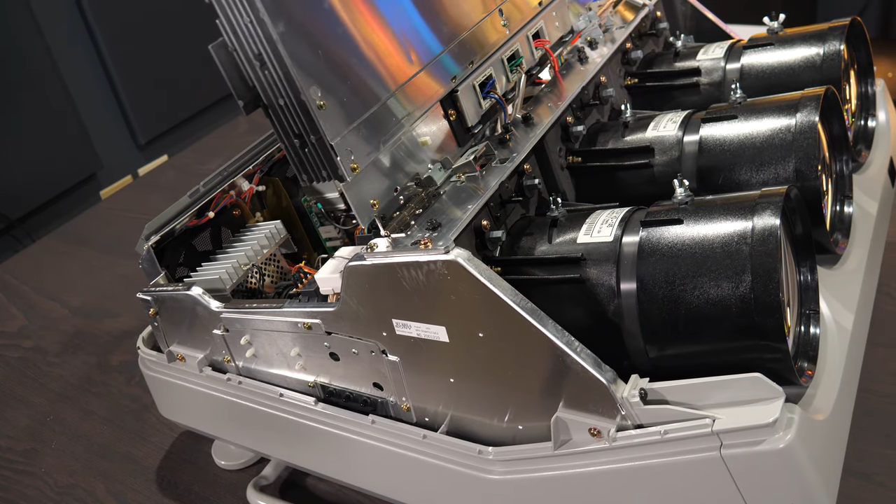
CRT monitors: there’s nothing quite like ’em. But did you know that video projectors used to use CRTs? A trio of monochrome CRTs, in fact: one for each color; red, green, and blue. By their powers combined, these monsters were capable of fantastic resolution and image quality. Despite being nowhere near as bright as modern projectors, after being properly set up, [Technology Connections] says it’s still one of the best projected images he has seen outside of a movie theatre.
After a twenty-minute startup to reach thermal equilibrium, one can settle down with a chunky service manual for a ponderous calibration process involving an enormous remote control. The reward is a fantastic (albeit brightness-limited) picture.
Still, these projectors had drawbacks. They were limited in brightness, of course. But they were also complex, labor-intensive beasts to set up and calibrate. On the other hand, at least they were heavy.
[Technology Connections] gives us a good look at the Sony VPH-D50HT Mark II CRT Projector in its tri-lobed, liquid-cooled glory. This model is a relic by today’s standards, but natively supports 1080i via component video input and even preserves image quality and resolution by reshaping the image in each CRT to perform things like keystone correction, thus compensating for projection angle right at the source. Being an analog device, there is no hint of screen door effect or any other digital artifact. The picture is just there, limited only by the specks of phosphor on the face of each tube.
Converging and calibrating three separate projectors really was a nontrivial undertaking. There are some similarities to the big screen rear-projection TVs of the 90s and early 2000s (which were then displaced by plasma and flat-panel LCD displays). Unlike enclosed rear-projection TVs, the screen for projectors was not fixed, which meant all that calibration needed to be done on-site. A walkthrough of what that process was like — done with the help of many test patterns and a remote control that is as monstrous as it is confusing — starts at 15:35 in the video below.
Like rear-projection TVs, these projectors were displaced by newer technologies that were lighter, brighter, and easier to use. Still, just like other CRT displays, there was nothing quite like them. And if you find esoteric projector technologies intriguing, we have a feeling you will love the Eidophor.
While our eyes are miraculous little devices, they aren’t very sensitive outside of the normal old red, green, and blue spectra. The camera in your phone is far more sensitive, and scientists want to use those sensors in place of expensive hyperspectral ones. Researchers at Purdue have a cunning plan: use a calibration card.
The idea is to take a snap of the special card and use it to understand the camera’s exact response to different colors in the current lighting conditions. Once calibrated to the card, they can detect differences as small as 1.6 nanometers in light wavelengths. That’s on par with commercial hyperspectral sensors, according to the post.
You may wonder why you would care. Sensors like this are useful for medical diagnostic equipment, analysis of artwork, monitoring air quality, and more. Apparently, high-end whisky has a distinctive color profile, so you can now use your phone to tell if you are getting the cheap stuff or not.
Do you calibrate your digital meters? Most of us don’t have the gear to do a proper calibration, but [Mike Wyatt] shares his simple way to calibrate his DMMs using a precision resistor coupled with a thermistor. The idea is to use a standard dual banana plug along with a 3D-printed housing to hold the simple electronics.
The calibration element is a precision resistor. But the assembly includes a 1% thermistor. In addition to the banana plugs, there are test points to access the resistor and another pair for the thermistor.
Most cheap wall clocks use very similar mechanisms based around the Lavet-type stepper motor. These are usually driven by a chip-on-board oscillator that may or may not be particularly accurate.
[Lauri] desired a way to tune up these cheap clocks by using GPS-level timing accuracy. Thus began a project based around a CY8KIT evaluation board from Cypress. The microcontroller is paired with a small character LCD as a user interface, and hooked up to a cheap GPS module with an accurate 1-pulse-per-second (1PPS) timing output. The concept is simple enough. Clock drift is measured by using counters in the microcontroller to compare the timing of the GPS 1PPS output and the pulses driving the Lavet-type stepper motor. The difference between the two can be read off the device, and used to determine if the wall clock is fast or slow. Then one need only use a trimmer capacitor to tweak the wall clock’s pulse rate in order to make it more accurate.
Few of us spend much time calibrating low-cost wall clocks to high levels of accuracy. If that sounds like a fun hobby to you, or your name is Garrus, you would probably find [Lauri]’s device remarkably useful. Believe it or not, this isn’t the first clock calibrator we’ve seen, either. Meanwhile, if you’ve brewed up your own high-accuracy timing hardware, feel free to let us know on the tipsline.
The difference between 3D printing and good 3D printing comes down to attention to detail. There are so many settings and so many variables, each of which seems to impact the other to a degree that can make setting things up a maddening process. That makes anything that simplifies the process, such as this computer vision pressure advance attachment, a welcome addition to the printing toolchain.
If you haven’t run into the term “pressure advance” for FDM printing before, fear not; it’s pretty intuitive. It’s just a way to compensate for the elasticity of the molten plastic column in the extruder, which can cause variations in the amount of material deposited when the print head acceleration changes, such as at corners or when starting a new layer.
To automate his pressure advance calibration process, [Marius Wachtler] attached one of those dirt-cheap endoscope cameras to the print head of his modified Ender 3, pointing straight down and square with the bed. A test grid is printed in a corner of the bed, with each arm printed using a slightly different pressure advance setting. The camera takes a photo of the pattern, which is processed by computer vision to remove the background and measure the thickness of each line. The line with the least variation wins, and the pressure advance setting used to print that line is used for the rest of the print — no blubs, no blebs.
We’ve seen other pressure-advanced calibrators before, but we like this one because it seems so cheap and easy to put together. True, it does mean sending images off to the cloud for analysis, but that seems a small price to pay for the convenience. And [Marius] is hopeful that he’ll be able to run the model locally at some point; we’re looking forward to that.
Like many of you, I have a bench full of electronic instruments. The newest is my Rigol oscilloscope, only a few years old, while the oldest is probably my RF signal generator that dates from some time in the early 1950s. Some of those instruments have been with me for decades, and have been crucial in the gestation of countless projects.
If I follow the manufacturer’s recommendations then just like that PAT tester I should have them calibrated frequently. This process involves sending them off to a specialised lab where their readings are compared to a standard and they are adjusted accordingly, and when they return I know I can trust their readings. It’s important if you work in an industry where everything must be verified, for example I’m certain the folks down the road at Airbus use meticulously calibrated instruments when making assemblies for their aircraft, because there is no room for error in a safety critical application at 20000 feet.