Makerpipe Turns Conduit Into Structures

At the risk of stating the obvious, building big things can be difficult. Sure, parts that fit on the bed of a 3D printer are easy to make, if not particularly fast, and scaling up from there is possible. But if you need a long beam or structural element, printing makes little sense; better to buy than build in that case. The trouble then becomes, how do you attach such parts together?

Enter Makerpipe. This South Carolina company, recently out of a crowdfunding campaign, makes a range of structural connectors and fittings for electrical mechanical tubing, or EMT, the galvanized steel conduit used in the electrical trades. EMT is widely available in multiple sizes and is relatively cheap, although we have noticed that the price here has ticked up quite a bit over the last couple of years. It also has the advantage of being available off-the-shelf at any big-box home improvement store, meaning you have instant access to a fantastic building material.

Makerpipe’s bolt-together couplings let you turn pieces of EMT, easily cut with a hacksaw or pipe cutter, into structures without the need for welding. Yes, you can do the same with extruded aluminum, but even if you’re lucky enough to live near a supply house that carries extrusions and the necessary fittings and is open on Saturday afternoon, you’ll probably pay through the nose for it.

Makerpipe isn’t giving their stuff away, and while we normally don’t like to feature strictly commercial products, something that makes building large structures easier and faster seems worth sharing with our community. We’ve done our share of fabricobbling together EMT structures after all, and would have killed for fittings like these.

Continue reading “Makerpipe Turns Conduit Into Structures”

Where Do You Connect The Shield?

When it comes to polarizing and confusing questions in electronics, wiring up shields is on the top-10 list when sorted by popularity. It’s a question most of us need to figure out at some point – when you place a USB socket symbol on your schematic, where do you wire up the SHIELD and MP pins?

Once you look it up, you will find Eevblog forum threads with dozens of conflicting replies, Stackexchange posts with seven different responses plus a few downvoted ones, none of them accepted, and if you try to consult the literature, the answer will invariably be “it depends”.

I’m not a connector-ground expert, I just do a fair bit of both reading and hacking. Still, I’ve been trying to figure out this debate, for a couple years now, re-reading the forum posts each time I started a new schematic with a yet-unfamiliar connector. Now, of course, coming to this question with my own bias, here’s a summary you can fall back on.

Consumer Ports

Putting HDMI on your board? First of all, good luck. Then, consider – do you have a reason to avoid connecting the shield? If not, certainly connect the shield to ground, use jumpers if that’s what makes you comfortable, though there’s a good argument that you should just connect directly, too. The reason is simple: a fair few HDMI cables omit GND pin connections, fully relying on the shield for return currents. When your HDMI connection misfires, you don’t want to be debugging your HDMI transmitter settings when the actual No Signal problem, as unintuitive as it sounds, will be simply your shield not being grounded – like BeagleBone and Odroid didn’t in the early days. By the way, is a DVI-D to HDMI adapter not working for you? Well, it might just be that it’s built in a cheap way and doesn’t connect the shields of the two sockets together – which is fixable.

Continue reading “Where Do You Connect The Shield?”

USB-C Power For Ham Radio

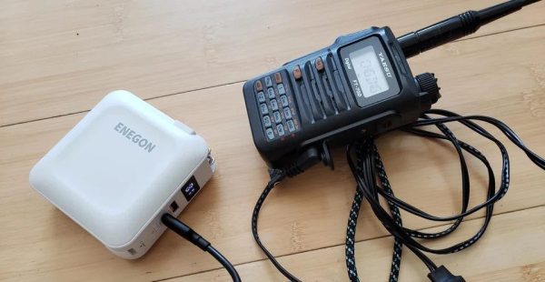
Even though manufacturers of handheld ham radios have been busy adding all sorts of bells and whistles into their portable offerings, for some reason, many of them lack a modern USB-C port. In the same vein, while some have USB for programming or otherwise communicating between the radio and a computer, very few can use USB for power. Instead , they rely on barrel jacks or antiquated charging cradles. If you’d like to modernize your handheld radio’s power source, take a look at what [jephthai] did to his Yaesu.

In the past, USB ports could be simply soldered onto a wire and used to power basically anything that took 5 VDC. But the radio in question needs 12 volts, so the key was to find a USB-C cable with the built-in electronics to negotiate the right amount of power from USB-PD devices. For this one, [jephthai] cut the barrel connector off his radio’s power supply and spliced in some Anderson power pole connectors so he could use either the standard radio charger or one spliced onto this special cable.

With this fairly simple modification out of the way, it’s possible to power the handheld radio for long outings with the proper USB battery bank on hand. For plenty of situations this is much preferable to toting around a 12 V battery, which was the method of choice for powering things like QRP rigs when operating off-grid.

Finessing A Soldering Iron To Remove Large Connectors

One of the first tools that is added to a toolbox when working on electronics, perhaps besides a multimeter, is a soldering iron. From there, soldering tools can be added as needed such as a hot air gun, reflow oven, soldering gun, or desoldering pump. But often a soldering iron is all that’s needed even for some specialized tasks as [Mr SolderFix] demonstrates.

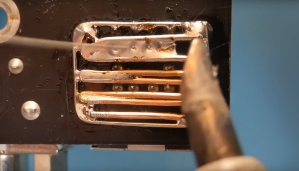
This specific technique involves removing a large connector from a PCB. Typically either a heat gun would be used, which might damage the PCB, or a tedious process involving a desoldering tool or braided wick might be tried. But with just a soldering iron, a few pieces of wire can be soldered around each of the pins to create a massive solder blob which connects all the pins of the connector to this wire. With everything connected to solder and wire, the soldering iron is simply pressed into this amalgamation and the connector will fall right out of the board, and the wire can simply be dropped away from the PCB along with most of the solder.

There is some cleanup work to do afterwards, especially removing excess solder in the holes in the PCB, but it’s nothing a little wick and effort can’t take care of. Compared to other methods which might require specialized tools or a lot more time, this is quite the technique to add to one’s soldering repertoire. For some more advanced desoldering techniques, take a look at this method for saving PCBs from some thermal stresses.

Continue reading “Finessing A Soldering Iron To Remove Large Connectors”

On the left, four through-hole USB-C connectors laid out on a purple cutting mat. On the right, a teardown picture shows that there's neither resistors nor CC connections inside such a connector, resulting in consequences described in the article.

The USB-C Connectors You Never Knew You Wanted To Avoid

On Tech Twitter, some people are known for Their Thing – for example, [A13 (@sad_electronics)], (when they’re not busy designing electronics), searches the net to find outstanding parts to marvel at. A good portion of the parts that they find are outstanding for all the wrong reasons. Today, that’s a through-hole two-pin USB Type-C socket. Observing the cheap tech we get from China (or the UK!), you might conclude that two 5.1K pulldown resistors are very hard to add to a product – this socket makes it literally impossible.

We’ve seen two-pin THT MicroUSB sockets before, sometimes used for hobbyist kits. This one, however, goes against the main requirement of Type-C connectors – sink (Type-C-powered) devices having pulldowns on CC pins, and source devices (PSUs and host ports) having pull up resistors to VBUS. As disassembly shows, this connector has neither of these nor the capability for you to add anything, as the CC pins are physically not present. If you use this port to make a USB-C-powered device, a Type-C-compliant PSU will not give it power. If you try to make a Type-C PSU with it, a compliant device shall (rightfully!) refuse to charge from it. The only thing this port is good for is when a device using it is bundled with a USB-A to USB-C cable – actively setting back whatever progress Type-C connectors managed to make.

As much as USB Type-C basics are straightforward, manufacturers get it wrong on the regular – back in 2016, a wrong cable could kill your $1.5k MacBook. Nowadays, we might only need to mod a device with a pair of 5.1K resistors every now and then. We can only hope that the new EU laws will force devices to get it right and stop ruining the convenience for everyone, so we can finally enjoy what was promised to us. Hackers have been making more and more devices with USB-C ports, and even retrofitting iPhones here and there. If you wanted to get into mischief territory and abuse the extended capabilities of new tech, you could even make a device that enumerates in different ways if you flip the cable, or make a “BGA on an FPC” dongle that is fully hidden inside a Type-C cable end!

Clever PCB Brings Micro USB To The Arduino Uno

Even with more and more devices making the leap to USB-C, the Arduino Uno still proudly sports a comparatively ancient Type-B port. It wouldn’t be a stretch to say that many Hackaday readers only keep one of these cables around because they’ve still got an Uno or two they need to plug in occasionally.

Looking to at least move things in the right direction, [sjm4306] recently set out to create a simple board that would let him mount a micro USB connector in place of the Uno’s original Type-B. Naturally there are no components on the PCB, it simply adapts the original through-hole footprint to the tight grouping of surface mount pads necessary to mount a female micro USB port.

Making castellated holes on the cheap.

The design is straightforward, but as [sjm4306] explains in the video below, there’s actually more going on here than you might think. Looking to avoid the premium he’d pay to have the board house do castellated holes, he cheated the system a bit by having the board outline go right through the center of the standard pads.

Under a microscope, you can see the downside of this approach. Some of the holes got pretty tore up as the bit routed out the edges of the board, with a few of them so bad [sjm4306] mentions there might not be enough of the pad left to actually use. But while they may not be terribly attractive, most of them were serviceable. To be safe, he says anyone looking to use his trick with their own designs should order more boards than they think they’ll actually need.

Of course you could go all the way and retrofit the Uno with a USB-C port, as we’ve seen done with devices in the past. But the latest-and-greatest USB interface can be a bit fiddly, especially with DIY gadgets, so we can’t blame him for going with the more reliable approach.

Continue reading “Clever PCB Brings Micro USB To The Arduino Uno”

Print-in-Place Connectors Aim To Make Wiring Easier

One thing some of us here in the United States have always been jealous of is the WAGO connectors that seem so common in electrical wiring everywhere else in the world. We often wonder why the electrical trades here haven’t adopted them more widely — after all, they’re faster to use than traditional wire nuts, and time is money on the job site.

Wago 221 compact lever connector via the Wago YouTube channel

This print-in-place electrical connector is inspired by the WAGO connectors, specifically their Lever Nut series. We’ll be clear right up front that [Tomáš “Harvie” Mudruňka’s] connector is more of an homage to the commercially available units, and should not be used for critical applications. Plus, as a 3D-printed part, it would be hard to compete with something optimized to be manufactured in the millions. But the idea is pretty slick. The print-in-place part has a vaguely heart-shaped cage with a lever arm trapped inside it.

After printing and freeing the lever arm, a small piece of 1.3-mm (16 AWG) solid copper wire is inserted into a groove. The wire acts as a busbar against which the lever arm squeezes conductors. The lever cams into a groove on the opposite wall of the cage, making a strong physical and electrical connection. The video below shows the connectors being built and tested.

We love the combination of print-in-place, compliant mechanisms, and composite construction on display here. It reminds us a bit of these printable SMD tape tamers, or this print-in-place engine benchmark.

Continue reading “Print-in-Place Connectors Aim To Make Wiring Easier”