This Debug Connector Brings Your Issues To The Edge

Given an unknown PCBA with an ARM processor, odds are good that it will have either the standard 10 pin 0.05″ or 20 pin 0.1″ debug connector. This uncommon commonality is a boon for an exploring hacker, but when designing a board such headers require board space in the design and more components to be installed to plug in. The literally-named Debug Edge standard is a new libre attempt to remedy this inconvenience.

The name “Debug Edge” says it all. It’s a debug, edge connector. A connector for the edge of a PCBA to break out debug signals. Card edge connectors are nothing new but they typically either slot one PCBA perpendicularly into another (as in a PCI card) or hold them in parallel (as in a mini PCIe card or an m.2 SSD). The DebugEdge connector is more like a PCBA butt splice.

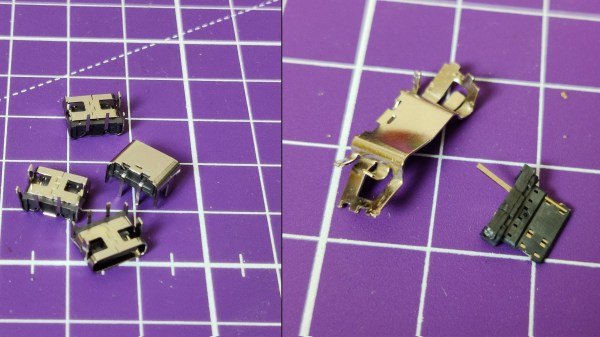
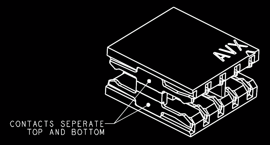
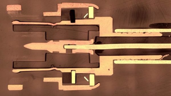
It makes use of a specific family of AVX open ended card edge connectors designed to splice together long rectangular PCBAs used for lighting end to end. These are available in single quantities starting as low as $0.85 (part number for the design shown here is 009159010061916). The vision of the DebugEdge standard is that this connector is exposed along the edge of the target device, then “spliced” into the debug connector for target power and debug.

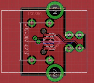
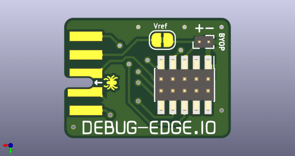
Right now the DebugEdge exists primarily as a standard, a set of KiCAD footprints, and prototype adapter boards on OSHPark (debugger side, target side). A device making use of it would integrate the target side and the developer would use the debugger side to connect. The standard specifies 4, 6, 8, and 10 pin varieties (mapping to sizes of available connector, the ‘010’ in the number above specifies pincount) offering increasing levels of connectivity up to a complete 1:1 mapping of the standard 10 pin ARM connector. Keep in mind the connectors are double sided, so the 4 pin version is a miniscule 4mm x 4.5mm! We’re excited to see that worm its way into a tiny project or two.

We’ve seen plenty of part-free debug and programming connectors before. Have a favorite? Let us know in the comments!

Milling A Custom 6-Pin DIN Connector

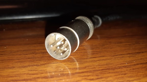
When [Charles Ouweland] found himself in need of a DIN connector that had a somewhat unusual pin arrangement, he figured he could fashion his own in less time than it would take to have a replacement shipped to him. In the end it sounds as though it took a lot longer than expected, but given the worldwide situation, we don’t doubt this bespoke connector was still put to work before its eBay counterpart would have arrived.

More importantly, the connector [Charles] produced looks fantastic. If we weren’t told otherwise, we’d have assumed the finished product was commercially produced. Although to be fair, he did have a little help there. The housing and pins themselves were pulled from a sacrificial connector; his primary contribution was the insulating block that holds the pins in their proper position.

So how did he make it? He had considered using a piece of scrap material and just putting the holes in it with a drill press, but he was worried getting the aliment right. Instead, he decided to call his cheap CNC router into service. By routing his design out of copper clad PCB, he was even able to tie the appropriate pins together right in the connector.

Admittedly, we don’t see a lot of hardware that still uses DIN connectors these days. But this tip is certainly worth filing away just in case. You never know when you might find an old piece of hardware that just needs a little TLC to get up and running again. Who knows, you might even find a dumpster full of them.

Magnets And Printed Parts Make Quick-Disconnect Terminals

The Apple MagSafe power connector is long gone from their product line, but that doesn’t mean that magnetic connectors aren’t without their charms. It just takes the right application, and finding one might be easier with these homebrew magnetic connectors.

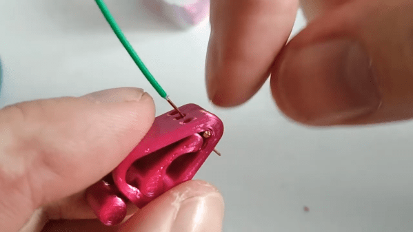
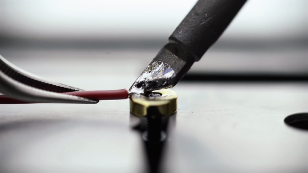
We’ll admit that the application that [Wesley Lee] found for his magnetic connectors is perhaps a little odd. He’s building something called Linobyte, a hybrid art and electronics project that pays homage to computing history with very high-style, interactive core memory modules. The connectors are for the sense wire that is weaved through the eight toroids on each module, to program it with a single byte. Each connector has a 3D-printed boot that holds a small, gold-plated neodymium magnet with the sense wire soldered to it. A socket holds another magnet to the underside of a PCB. The magnet in the boot sticks to the PCB and makes contact with pads, completing the circuit. We know what you’re thinking: heating a magnet past the Curie point is a great way to ruin it. [Wesley] admits that happens, but it just makes the connection a little weaker, which works for his application. The short video below shows how he puts them together.

We can think of a couple of ways these connectors would be useful, and we really like the look of the whole project. It’ll be interesting to see where it goes, but in the meantime, brushing up on how magnets work could be fun. Continue reading “Magnets And Printed Parts Make Quick-Disconnect Terminals”

The BNC Connector And How It Got That Way

When I started working in a video production house in the early 1980s, it quickly became apparent that there was a lot of snobbery in terms of equipment. These were the days when the home video market was taking off; the Format War had been fought and won by VHS, and consumer-grade VCRs were flying off the shelves and into living rooms. Most of that gear was cheap stuff, built to a price point and destined to fail sooner rather than later, like most consumer gear. In our shop, surrounded by our Ikegami cameras and Sony 3/4″ tape decks, we derided this equipment as “ReggieVision” gear. We were young.

For me, one thing that set pro gear apart from the consumer stuff was the type of connectors it had on the back panel. If a VCR had only the bog-standard F-connectors like those found on cable TV boxes along with RCA jacks for video in and out, I knew it was junk. To impress me, it had to have BNC connectors; that was the hallmark of pro-grade gear.

I may have been snooty, but I wasn’t really wrong. A look at coaxial connectors in general and the design decisions that went into the now-familiar BNC connector offers some insight into why my snobbery was at least partially justified.

Continue reading “The BNC Connector And How It Got That Way”

The Modular Connector And How It Got That Way

They adorn the ends of Cat5 network patch cables and the flat satin cables that come with all-in-one printers that we generally either toss in the scrap bin or throw away altogether. The blocky rectangular plugs, molded of clear plastic and holding gold-plated contacts, are known broadly as modular connectors. They and their socket counterparts have become ubiquitous components of the connected world over the last half-century or so, and unsurprisingly they had their start where so many other innovations began: from the need to manage the growth of the telephone network and reduce costs. Here’s how the modular connector got that way.

Continue reading “The Modular Connector And How It Got That Way”

MIDI Association Releases Spec For TRS Jacks

The MIDI spec was released in 1983, and for more than thirty years every synthesizer, drum machine, and piece of computer hardware with MIDI has sported an enormous DIN-5 jack on the back. Why did they choose such a large connector? Well, MiniDIN connectors hadn’t even been invented yet, and today even MiniDIN connectors are rarely-seen, obsolete connectors.

In the last decade, MIDI has found its way into some very small machines. Those Pocket Operators have MIDI sync, you can control a Game Boy with MIDI using the right hardware, and the cute little Korg synths also have MIDI tucked away in there somewhere. You can’t put a DIN-5 jack on those things, leading to some weird implementations of MIDI over non-standard connectors.

Now the MIDI Association has weighed in on the situation. There’s now a spec for MIDI over 2.5mm and 3.5mm TRS jacks. In just a few short decades, you’ll be able to connect MIDI gear with an audio aux cable.

Although there are five connectors in a DIN-5 jack, most implementations use only two connectors to send and receive data. Synth manufacturers have capitalized on this fact and cheap TRS connectors to build their own implementation of MIDI using smaller connectors, sometimes with incompatable pinouts.

Now, though, there’s a standard. For TRS connectors, the tip is pin 5 on the DIN-5, the ring is pin 4, and the sleeve is pin 2. It sends and receives data to synths and drum machines from 1983, and it doesn’t use gigantic connectors.

The only caveats to the new MIDI standard is that 2.5mm TRS connectors are recommended, and that protection circuitry is strongly recommended in the case a headphone driver is inevitably connected to a MIDI device. Other than that, everything’s coming up roses, and this opens up the door to MIDI jacks that are much, much easier to source.

The Electrical Outlet And How It Got That Way

Right now, if you happen to be in Noth America, chances are pretty good that there’s at least one little face staring at you. Look around and you’ll spy it, probably about 15 inches up from the floor on a nearby wall. It’s the ubiquitous wall outlet, with three holes arranged in a way that can’t help but stimulate the facial recognition firmware of our mammalian brain.

No matter where you go you’ll find those outlets and similar ones, all engineered for specific tasks. But why do they look the way they do? And what’s going on electrically and mechanically behind that familiar plastic face? It’s a topic we’ve touched on before with Jenny List’s take on international mains standards. Now it’s time to take a look inside the common North American wall socket, and how it got that way.

Continue reading “The Electrical Outlet And How It Got That Way”