Of all the methods of making big pieces of metal into smaller pieces of metal, perhaps none is more interesting than electrical discharge machining. EDM is also notoriously fussy, what with having to control an arc discharge while precisely positioning the tool relative to the workpiece. Still, some home gamers give it a whirl, and we love to share their successes, like this work-in-progress EDM machine. (Video, embedded below.)
We’ve linked [Andy]’s first videos below the break, and we’d expect there will be a few more before all is said and done. But really, for being fairly early in the project, [Andy] has made a lot of progress. EDM is basically using an electric arc to remove material from a workpiece, but as anyone who has unintentionally performed EDM on, say, a screwdriver by shorting it across the terminals in a live outlet box, the process needs to be controlled to be useful.
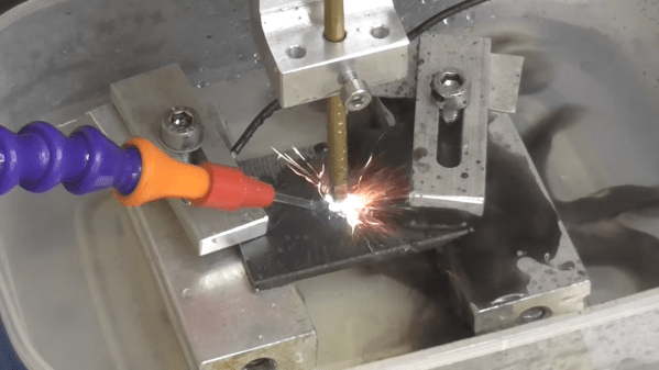
Part 1 shows the start of the build using an old tap burning machine, a 60-volt power supply, and a simple pulse generator. This was enough to experiment with the basics of both the mechanical control of electrode positioning, and the electrical aspects of getting a sustained, useful discharge. Part 2 continues with refinements that led very quickly to the first useful parts, machined quickly and cleanly from thin stock using a custom tool. We’ll admit to being impressed — many EDM builds either never get to the point of making simple holes, or stop when progressing beyond that initial success proves daunting. Of course, when [Andy] drops the fact that he made the buttons for the control panel on his homemade injection molding machine, one gets the feeling that anything is possible.
We’re looking forward to more on this build. We’ve seen a few EDM builds before, but none with this much potential.
Continue reading “Homemade EDM Machine Moves From Prototype To Production”