Tiny Laser Cutter Puts Micro Steppers To Work

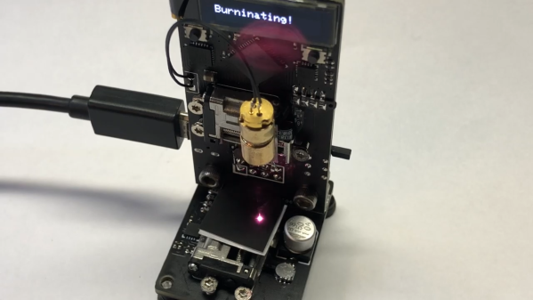
The influx of cheap laser cutters from China has been a boon to the maker movement, if at the cost of a lot of tinkering to just get the thing to work. So some people just prefer to roll their own, figuring that starting from scratch means you get exactly what you want. And apparently what [Mike Rankin] wanted was a really, really small laser cutter.

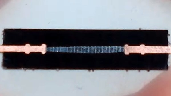
The ESP32 Burninator, as [Mike] lovingly calls his creation, is small enough to be in danger of being misplaced accidentally. The stage relies on tiny stepper-actuated linear drives, available on the cheap from AliExpress. The entire mechanical structure is two PCBs — a vertical piece that holds the ESP32, an OLED display, the X-axis motor, and the driver for the laser, which comes from an old DVD burner; a smaller bottom board holds the Y-axis and the stage. “Stage” is actually a rather grand term for the postage-stamp-sized working area of this cutter, but the video below shows that it does indeed cut black paper.

The cuts are a bit wonky, but this is surely to be expected given the running gear, and we like it regardless. It sort of reminds us of that resin 3D-printer small enough to fit in a Christmas ornament that [Sean Hodgins] did a while back. We’d suggest not trying to hang this on a tree, though.

Continue reading “Tiny Laser Cutter Puts Micro Steppers To Work”

Diode Basics By [W2AEW]

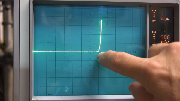
We didn’t think we needed a basic guide to diodes until we saw it was from [W2AEW], and then we knew we’d pick up some new things. Entitled “Diodes from Ideal to Real” the 18-minute video doesn’t disappoint with a mix of notes and time with a curve tracer to learn all about these devices.

As is typical for a [W2AEW] video this doesn’t just cover the simple operation of diode. It includes topics such as dynamic resistance, junction capacitance, and talks about a wide variety of diode types.

Continue reading “Diode Basics By [W2AEW]”

Negative Voltage Pushes AVR To New Heights

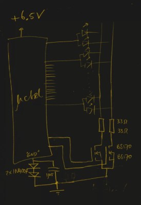
If we say that a hacker is somebody who looks at a “solved” problem and can still come up with multiple alternative solutions, then [Charles Ouweland] absolutely meets the grade. Not that we needed more evidence of his hacker cred given what we’ve seen from him before, but he recently wrote in to tell us about an interesting bit of problem solving which we think is a perfect example of the principle. He wanted to drive a salvaged seven segment LED display with an AVR microcontroller, but there was only one problem: the display needs 15V but the AVR is only capable of 5V. So what to do?

As it turns out, the first step to solving the problem was verifying there was actually a problem to begin with. [Charles] did some experimentation and found that the display didn’t actually need 15V to operate, and in fact would light up well enough at just 6.5V. This lowered the bar quite a bit, but it was still too high to power directly from the chip.

There were a few common ways to solve this problem, which no doubt the Hackaday reader is well aware of. But [Charles] wanted to take the path less traveled. More specifically, the path with the least amount of additional components he had to put on his PCB. He set out to find the absolute easiest way to make his 5V AVR light up a 6.5V LED, and ended up coming with a very clever solution that some may not even know is possible.

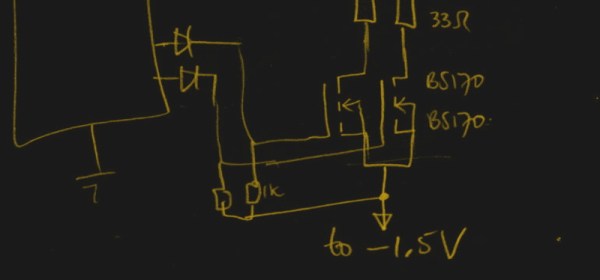
He reasoned that if he connected the source pins of two BS170 MOSFETs to a voltage of -1.5V, even when the AVR pin was 0V, they would be still be receiving 1.5V. This virtual “step ladder” meant that once the AVR’s pin goes high (5V), the relative voltage would actually be 6.5V and enough to drive his LEDs. Of course the only problem with that is that you need to have a source for -1.5V.

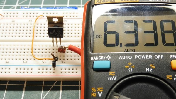
Getting a negative voltage would normally require adding more components to the design (which he set out to avoid in the first place), but then he came up with another clever idea. To pull the trick off, he actually feeds the AVR 6.5V, but raises the ground voltage by 1.5V with the addition of two 1N4007 diodes. This way the AVR gets a voltage within its capabilities and still can provide a relative 6.5V to the LEDs.

One might say [Charles] took the Kobayashi Maru approach, and simply redefined the rules of the game. But such is the power of the confounding negative voltage.

Science Shows Green Lasers Might Be More Than You Bargained For

This may come as a shock, but some of those hot screaming deals on China-sourced gadgets and goodies are not all they appear. After you plunk down your pittance and wait a few weeks for the package to arrive, you just might find that you didn’t get exactly what you thought you ordered. Or worse, you may get a product with unwanted bugs features, like some green lasers that also emit strongly in the infrared wavelengths.

Sure, getting a free death ray in addition to your green laser sounds like a bargain, but as [Brainiac75] points out, it actually represents a dangerous situation. He knows whereof he speaks, having done a thorough exploration of a wide range of cheap (and not so cheap) lasers in the video below. He explains that the paradox of an ostensibly monochromatic source emitting two distinct wavelengths comes from the IR laser at the heart of the diode-pumped solid state (DPSS) laser inside the pointer. The process is only about 48% efficient, meaning that IR leaks out along with the green light. The better quality DPSS laser pointers include a quality IR filter to remove it; cheaper ones often fail to include this essential safety feature. What wavelengths you’re working with are critical to protecting your eyes; indeed, the first viewer comment in the video is from someone who seared his retina with a cheap green laser while wearing goggles only meant to block the higher frequency light.

It’s a sobering lesson, but an apt one given the ubiquity of green lasers these days. Be safe out there; educate yourself on how lasers work and take a look at our guide to laser safety. Continue reading “Science Shows Green Lasers Might Be More Than You Bargained For”

Diode Recovery Time Explained

There are at least two phases to learning about electronics. In the first phase, you learn about how components are supposed to work. In the second phase, you learn about how they really work. Wires have resistance and inductance. Adjacent wires have capacitance. Capacitors leak. Inductors have resistance. All of these things matter. [Learnelectronics] has a recent video that explores recovery time for a diode — a phase two conversation.

If you haven’t run into recovery time before, it is the amount of time the diode takes to shut off after it is conducting. This manifests itself as a little undershoot where the signal that the diode should block leaks through briefly.

Continue reading “Diode Recovery Time Explained”

Robert Hall And The Solid-State Laser

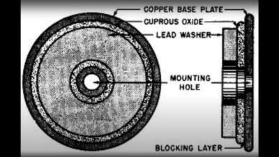
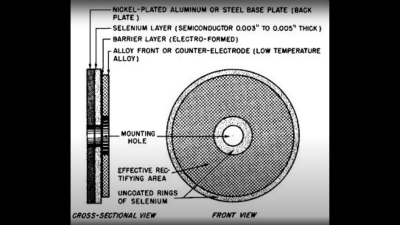
The debt we all owe must be paid someday, and for inventor Robert N. Hall, that debt came due in 2016 at the ripe age of 96. Robert Hall’s passing went all but unnoticed by everyone but his family and a few close colleagues at General Electric’s Schenectady, New York research lab, where Hall spent his remarkable career.

That someone who lives for 96% of a century would outlive most of the people he had ever known is not surprising, but what’s more surprising is that more notice of his life and legacy wasn’t taken. Without his efforts, so many of the tools of modern life that we take for granted would not have come to pass, or would have been delayed. His main contribution started with a simple but seemingly outrageous idea — making a solid-state laser. But he ended up making so many more contributions that it’s worth a look at what he accomplished over his long career.

Continue reading “Robert Hall And The Solid-State Laser”

Two-Cent Temperature Sensors

When they need to add temperature control to a project, many hackers reach for a K-type thermocouple for their high-temperature needs, or an integrated temperature-sensing IC when it doesn’t get that hot. The thermocouple relies on very small currents and extremely high gain, and you pretty much need a dedicated IC to read it, which can be expensive. The ICs aren’t as expensive, but they’re basically limited to boiling water. What do you do if you want to control a reflow oven?

There’s a cheaper way that spans a range between Antarctic winter and molten solder, and you’ve probably already got the parts on your shelf. Even if you don’t, it’s only going to run you an extra two cents, assuming that you’ve already got a microcontroller with an ADC in your project. The BOM: a plain-vanilla diode and a resistor.

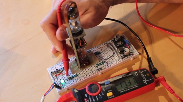
I’ve been using diodes as temperature sensors in three projects over the last year: one is a coffee roaster that brings the beans up to 220 °C in hot air, another is a reflow hotplate that tops out around 210 °C, and the third is a toner-transfer iron that holds a very stable 130 °C. In all of these cases, I don’t really care about the actual numerical value of the temperature — all that matters is reproducibility — so I never bothered to calibrate anything. I thought I’d do it right for Hackaday, and try to push the humble diode to its limits for science.

What resulted was a PCB fire, test circuits desoldering themselves above 190 °C, temperature probes coming loose, and finally a broken ramekin and 200 °C peanut oil all over my desk. Fun times! On the other hand, I managed to get out enough data to calibrate some diodes, and the results are fantastic. The circuits under test included both best practices and the easiest thing that could possibly work, and the results are pretty close. This is definitely a technique that you want to have under your belt for most temperature ranges. The devil is in the details, of course, so read on!

Continue reading “Two-Cent Temperature Sensors”