LinuxCNC contributor and machining enthusiast [Andy Pugh] is certainly not afraid to try making specialised tools to see how well they work out, and this time he’s been busy making a touch probe (video, embedded below) for checking the accuracy of machining operations and general measuring applications.
These things are not cheap, since they are essentially ‘just’ a switch with a long probe, But, as with anything specialised and machined with tight tolerances, you can understand why they cost what they do.
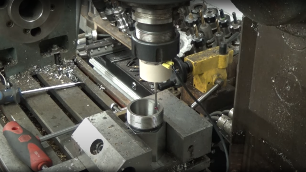
After inspecting and spending some time reverse-engineering such a unit, [Andy] then proceeded to grab some PEEK bar he had lying around and chuck it into the lathe (get it?). He notes Delrin would be more cost effective for those wishing to reproduce this, but as long as you have the ability to machine it and it’s non-conductive, there are many other options you could try.
Using no special tools other than a collet block (like this one) all the angled holes and slots were made with ease, with the help of a specially 3D-printed mount for the vise. A nice, simple approach, we think!
[Andy] tested the repeatability of the probe, mounted over his CNC-converted Holbrook lathe, reporting a value of 1 um, which seems rather good. Centering of the probe tip within the probe body was off a bit, as you’d expect for something made practically by hand, but that is less of a problem as it would seem, as it results in a fixed offset that can be compensated for in software. Perhaps the next version will have some adjustability to dial that out manually?
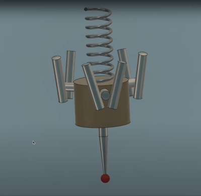
The whole assembly is formed from two plastic parts, a handful of ground-finished hardened steel pins, and a big spring. The only part remotely special is an off-the-shelf probe tip. During the electrical hookup, you may notice the use of a self-fluxing verowire pen, which was something this scribe didn’t know existed and has already placed an order for!
The reference 3D model for the design is shared from [Andy]’s Autodesk Drive for your viewing pleasure.
Of course, this isn’t the first DIY touch probe we’ve seen, here’s one for example, and over on Hackaday.IO, here’s an attempt to make one using a piezoelectric transducer.
Continue reading “A Simple Touch Probe Made With Basic Tools”