3D Printer Tool: Set Your Extruder Steps With Ease

My printer has other issues that i'm still tuning out, but the warping in PLA and excessive surface roughness has all the signs of over extrusion.
My printer has other issues that I’m still tuning out, but the warping in PLA and excessive surface roughness has all the signs of over extrusion.

I have an old Prusa i2 that, like an old car, has been getting some major part replacements lately after many many hours of service. Recently both the extruder and the extruder motor died. The extruder died of brass fill filament sintering to the inside of the nozzle (always flush your extruder of exotic filaments). The motor died at the wires of constant flexing. Regardless, I replaced the motors and found myself with an issue; the new motor and hotend (junk motor from the junk bin, and an E3D v6, which is fantastic) worked way better and was pushing out too much filament.

The hotend, driver gear, extruder mechanics, back pressure, motor, and plastic type all work together to set how much plastic you can push through the nozzle at once. Even the speed at which the plastic is going through the nozzle can change how much friction that plastic experiences. Most of these effects are somewhat negligible. The printer does, however, have a sort of baseline steps per mm of plastic you can set.

The goal is to have a steps per mm that is exactly matched to how much plastic the printer pushes out. If you say 10mm, 10mm of filament should be eaten by the extruder. This setting is the “steps per mm” in the firmware configuration. This number should be close to perfect. Once it is, you can tune it by setting the “extrusion multiplier” setting in most slicers when you switch materials, or have environmental differences to compensate for.

This little guy lets you tune the steps per mm exactly.

The problem comes in measuring the filament that is extruded. Filament comes off a spool and is pulled through an imprecisely held nozzle in an imprecisely made extruder assembly. On top of all that, the filament twists and curves. This makes it difficult to hold against a ruler or caliper and get a trustworthy measurement.

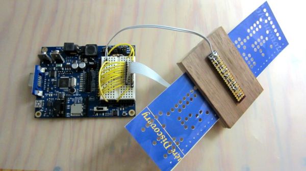
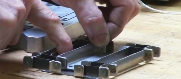
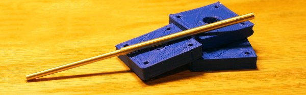
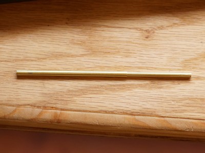
I have come up with a little measuring device you can make with some brass tubing, sandpaper, a saw (or pipe cutter), a pencil torch, solder, and some calipers. To start with, find two pieces of tubing. The first’s ID must fit closely with the filament size you use. The second tube must allow the inside tubing to slide inside of it closely. A close fit is essential.

Continue reading “3D Printer Tool: Set Your Extruder Steps With Ease”

Crappy Robots And Even Crappier Electronics Kits

Robots and DIY electronics kits have a long history together. There probably isn’t anyone under the age of forty that hasn’t had some experience with kit-based robots like wall-hugging mouse robots, a weird walking robot on stilts, or something else from the 1987 American Science and Surplus catalog. DIY robot kits are still big business, and walking through the sales booths of any big Maker Faire will show the same ideas reinvented again and again.

[demux] got his hands on what is possibly the worst DIY electronics kit in existence. It’s so incredibly bad that it ends up being extremely educational; pick up one of these ‘introduction to electronics’ kits, and you’ll end up learning advanced concepts like PCB rework, reverse engineering, and Mandarin.

Continue reading “Crappy Robots And Even Crappier Electronics Kits”

Make PCBs With DLP, OMG!

There’s so many ways to skin the home-fabrication-of-PCBs cat! Here’s yet another. [Nuri Erginer] had a DLP projector on hand, and with the addition of some reducing optics, managed to turn it into a one-shot PCB exposer.

If you’ve ever used photo-resist PCB material before, you know the drill: print out your circuit onto transparency film, layer the transparency with the sensitized PCB, expose with a UV light for a while, dissolve away the unexposed resist, and then etch. Here, [Nuri] combines the first three steps in one by exposing the board directly from a DLP projector.

The catch is that the projector’s resolution limits the size of the board that you can make. To fab a board that’s 10cm x 10cm, at XGA resolution (1024×768), you’ll end up with a feature size of around 0.004″ in the good direction and 0.005″ in the other.

For DIP parts, that’s marginal, but for fine-pitch or small SMT parts, that won’t do. On the other hand, for a smaller board, optimally one in the same 4:3 ratio, it could work. And because it exposes in one shot, you can’t beat the speed. Cool hack, [Nuri]!

When you need more precision, strapping a UV laser to an accurate 2D robot is a good way to go, but it’s gonna take a while longer.

Heathkit’s Triumphant Return?

Heathkit, the storied purveyor of high-quality DIY electronics kits that inspired a generation of enthusiasts and launched the careers of many engineers, has returned from the dead. We think. At least it seems that way from this build log by [Spritle], an early adopter of the rebooted company’s first offering. But if [Spritle]’s experience is any indication, Heathkit has a long way to go to recreating its glory days. Continue reading “Heathkit’s Triumphant Return?”

No User Serviceable Parts Inside? The Rise Of The Fix-It Culture

pix-tv-repair-shop
[Source: 1950s Television]
My first job out of high school was in a TV shop. I was hired mainly for muscle; this was the early 1980s and we sold a lot of console TVs that always seemed to need to be delivered to the third floor of a walk up. But I also got to do repair work on TVs and stereos, and I loved it. Old TVs from the 60s and 70s would come in, with their pre-PCB construction and hand-wired chassis full of terminal strips and point to point wiring that must have been an absolute nightmare to manufacture. We’d replace dodgy caps, swap out tubes, clean the mechanical tuners, and sometimes put a new picture tube in  – always the diagnosis that customers dreaded the most, like being told they’d need a heart transplant. We kept those old sets alive, and our customers felt like they were protecting their investment in their magnificent Admiral or Magnavox console with the genuine – and very, very heavy – walnut cabinet.

I managed to learn a lot from my time as a TV repairman, and I got the bug for keeping things working well past the point which a reasonable person would recognize as the time to go shopping for a new one. Fixing stuff is where I really shine, and my house is full of epic (in my mind, at least) repairs that have saved the family tens of thousands of dollars over the years. Dishwasher making a funny noise? I’ll just pull it out to take a look. You say there’s a little shimmy in the front end when you brake? Pull the car into the garage and we’ll yank the wheels off. There’s basically nothing I won’t at least try to fix, and more often than not, I succeed.

I assumed that my fix-it bug made me part of a dying breed of cheapskates and skinflints, but it appears that I was wrong. The fix-it movement seems to be pretty healthy right now, fueled in part by the explosion in information that’s available to anyone with basic internet skills.

Continue reading “No User Serviceable Parts Inside? The Rise Of The Fix-It Culture”

DIY Punch Card System Despite Hanging Chads

Sometimes you just have parts lying around and want to make something out of them. [Tymkrs] had a robot paper cutter, so naturally they made punch cards. But then, of course, they needed a punch card reader, so they made one of those too. All with stuff lying around the shop.

The Silhouette Portrait paper cutter is meant for scrapbooking, but what evokes memories of the past more than punchcards? To cut out their data, rather than cute kittens or flowers, they wrote some custom code to turn ASCII characters into rows of dots. And the cards are done — you just have to clean up the holes that didn’t completely cut. These are infamously known as hanging chads.

The reader is made up of a block of wood, with a gap for the cards and perpendicular holes drilled for LEDs and photoresistors. This is cabled to a Propeller dev board with some simple firmware. We would have used photodiodes or phototransistors, because that’s what’s in our junk box (and because they have faster reaction time), but when you’ve got lemons, make lemonade.

OK, now that you’ve got a punch card reader and writer, what do you do with it? Password storage comes to mind.

Continue reading “DIY Punch Card System Despite Hanging Chads”

Learn 40 Years Of Mech Prototyping At Lightspeed

So, what are you doing for the next five and a half hours?  If you’re as busy as we are, you might have to digest this amazing 18 part series of videos over the course of a week or so, but we can almost guarantee you’ll learn a lot. It’s a speedrun through the best collection of Mechanical Engineering knowledge we’ve every come across.

In this epic Youtube video series [Dan Gelbart] shares his knowledge of 40 years of prototyping mechanical designs in a way we’ve never seen before. Not only does he show you how to build things, but he gives away a life time of “tips and tricks” that only a veteran builder would know. There are so many little gems of wisdom in this video series, it’s hard to know where to start with our description. He covers all the usual topics: everything from materials, adhesives, coatings, and such. But the real value of this series is all the little trinkets of information he shares along the way.

Don’t be intimated by some of the tools he’s using – chances are there is a DIY version of the piece of equipment out there, and often you can find a hackerspace or enthusiast in the area who will help you out with their gear. We think this video series should be a must watch for any engineering student or hacker. We made a video playlist for you so you can start watching the videos after the break.

Continue reading “Learn 40 Years Of Mech Prototyping At Lightspeed”