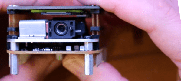
Who doesn’t want a pocket protectorprojector? Nothing will impress a date more than being able to whip out a PowerPoint presentation of your latest trip to the comic book convention. The key to [MickMake] build is the $100 DLP2000EVM evaluation module from Texas Instruments. This is an inexpensive light engine, and perfect for rolling your own projector. You can see the result in the video below.
If you don’t need compactness, you could drive the module with any Rasberry Pi or even a regular computer. But to get that pocket form factor, a Pi Zero W fits the bill. A custom PCB from [MickMake] lets the board fit in with the DLP module in a very small form factor.
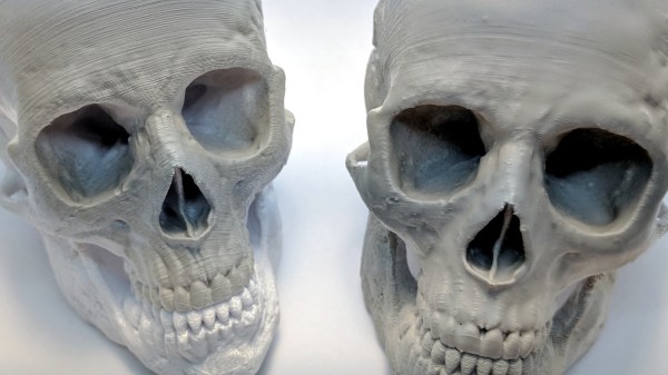
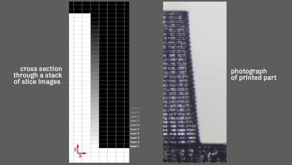
Smoothing the layer lines out of filament-based 3D prints is a common desire, and there are various methods for doing it. Besides good old sanding, another method is to apply a liquid coating of some kind that fills in irregularities and creates a smooth surface. There’s even a product specifically for this purpose: XTC-3D by Smooth-on. However, I happened to have access to the syrup-thick UV resin from an SLA printer and it occurred to me to see whether I could smooth a 3D print by brushing the resin on, then curing it. I didn’t see any reason it shouldn’t work, and it might even bring its own advantages. Filament printers and resin-based printers don’t normally have anything to do with one another, but since I had access to both I decided to cross the streams a little.
The UV-curable resin I tested is Clear Standard resin from a Formlabs printer. Other UV resins should work similarly from what I understand, but I haven’t tested them.
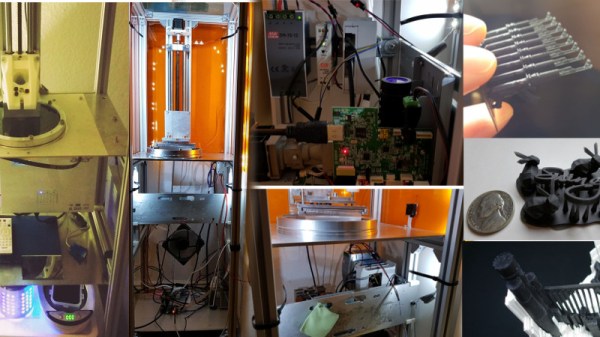
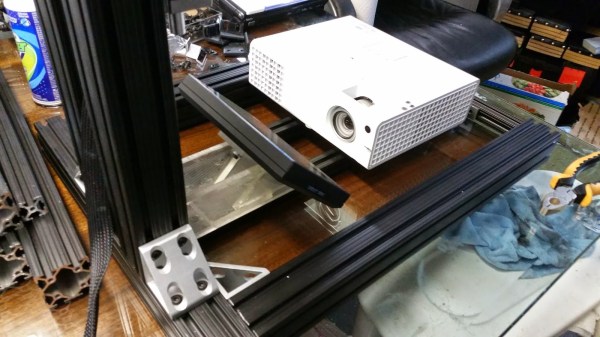
The 3D printing revolution is upon us and the technologies associated with these machines is evolving every day. Stereolithography or SLA printers are becoming the go-to printer for high-resolution prints that just can’t be fabricated on a filament-based machine. ADAM DLP 3D printer project is [adambrx]’s entry into the Hackaday Prize and the first step in his quest for higher quality prints on a DIY budget.
[adambrx]’s current iteration employs a Raspberry Pi 3 and a UV DLP Projector, all enclosed in a custom frame assembly. The logs show the evolution of the printer from an Acer DLP to the current UV DLP Light Engine. The results are quite impressive for a DIY project, and [adambrx] has put up images of 50-micrometer pillars and some nifty other prints which show the amount of work that has been put into the project.
It is safe to say that [adambrax] has outspent the average entry to the Hackaday Prize with over €5000 spent in around 3 years. Can [adambrx] can keep this one true to its DIY roots is yet to be seen, however, it is clear that this project has potential. We would love to see a high-resolution SLA printer that does not cost and arm and a leg.
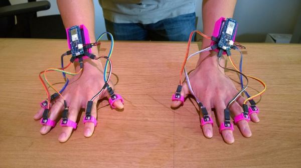
Watching Tony Stark wave his hands to manipulate projected constructs is an ever-approaching reality — at least in terms of gesture-tracking. Lift — a prototype built by a team from UC Irvine and FX Palo Alto Laboratory — is able to track up to ten fingers with 1.7 mm accuracy!
Lift’s gesture-tracking is achieved by using a DLP projector, two Arduino MKR1000s, and a light sensor for each digit. Lift’s design allows it to work on virtually any flat surface; the projected image acts as a grid and work area for the user. As their fingers move across the projected surface, the light sensors feed the information from the image to the Arduinos, which infers the location of each finger and translate it into a digital workspace. Sensors may also be mounted on other objects to add functionality.
So far, the team has used Lift as an input device for drawing, as well as using it to feign gesture controls on a standard laptop screen. The next step would be two or more projectors which would allow Lift to function fully and efficiently in three dimensions and directly interacting with projected media content. Can it also operate wirelessly? Yes. Yes, it can.
A DLP 3D printer works by shining light into a vat of photosensitive polymer using a Digital Light Processing projector, curing a thin layer of the goo until a solid part has been built up. Generally, the resolution of the print is determined by the resolution of the projector, and by the composition of the polymer itself. But, a technique posted by Autodesk for their Ember DLP 3D Printer could allow you to essentially anti-alias your print, further increasing the effective resolution.
We suppose [Dan Beaven] got up one day and said, “I’ll make my own resin 3D printer, with resin management and an advanced separation mechanism!” It’s a build log that shows just how possible it is to roll your own resin printer.
Prints on a dime!
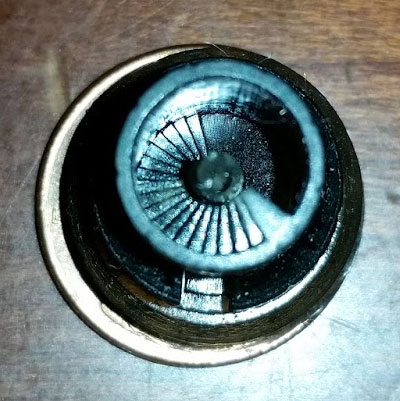
The machine isn’t finished yet, but the example prints coming off it are already very impressive. [Dan] stopped the print midway to get this photo of the detail on the stairs in the standard rook torture test.
[Dan] wants a lot of features from his machine that some of the more polished commercial printers are only now offering. One really nice one is the sliding and twist separation instead of tilt. This will allow for cleaner separation between layers during a print, a lower failure rate, and also faster print times.
He also added resin management with a peristaltic pump. This reduces the size of the build vat, and less resin will be exposed to the elements and wasted. It also means that the printer can run unattended. In the resin handling area of the printer he’s also added a carbon air filter. This lets him run higher performing resins without gassing him out of house and home with fumes.
We like how [Dan] just runs right ahead and puts the printer together. He even points out kludges on the machine that are holding it together long enough for him to print a more functional part for the 3D printer– on the 3D printer. We look forward to the next installment.
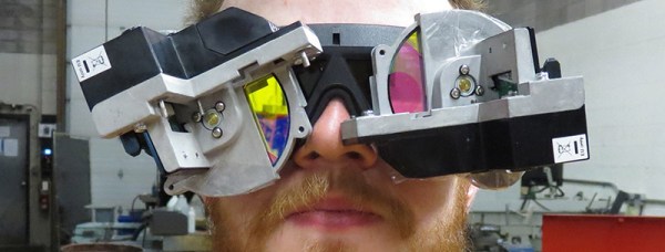
About five percent of the population is colorblind to one degree or another, and for them seeing the entire spectrum from Roy to Biv is simply impossible. Their eyes simply don’t have the cones to detect certain colors. The brain is the weirdest machine on the planet, though, and with the right tricks of light, even the colorblind can see more colors than they’re accustomed to. That’s the idea behind [PointyOintment]’s entry for the 2016 Hackaday Prize: color blindness correcting goggles.
Any device that claims to correct color blindness comes with a few caveats and a slightly loose interpretation of what ‘color blindness correcting’ actually is. For the same reason you can’t see deep infrared, someone with color blindness cannot distinguish between two colors; the eye simply doesn’t have the sensors to see a specific color of light. This doesn’t mean the ability to distinguish color in color blind individuals can’t be improved, though. The EnChroma glasses use an optical notch filter to block all colors between blue and green, and between green and red. This works, because the human brain is weird enough and can adapt to nearly anything.
[PointyOintmen] isn’t going with an optical notch filter. He’s using spinning color discs from a DLP projector and 3D ‘shutter’ glasses to present the world in different shades of color many times a second. It’s weird, untested, and will take a few hours to get used to, but it is a very interesting idea. Will it allow color blind people to see more colors? That’s a semantic issue, but if you define ‘seeing color’ as being able to differentiate between two different colors, yes, it will.