Here at Hackaday we cast a wary eye at tips that come in with superlative claims. Generally, if we post something that claims to be the fastest or the smallest of all time, we immediately get slapped down in the comments by someone who has done it faster or smaller. So we present the simplest TTL video card ever knowing the same thing will happen, but eager to see how anyone might scale things down.
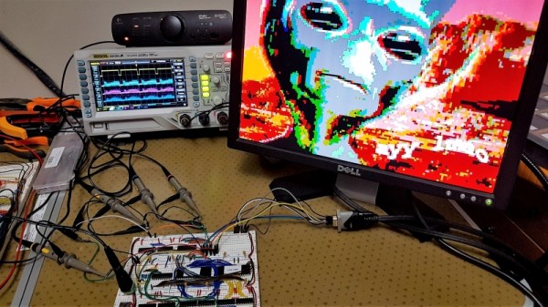
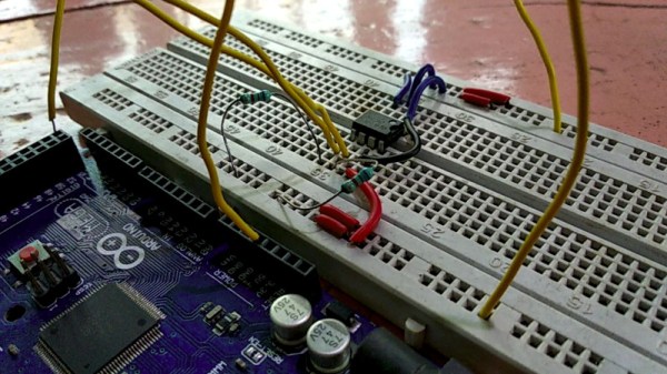
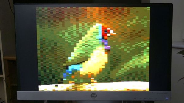
To be fair, [George Foot] does qualify his claim to the simplest usable VGA adapter, and he does note that it descends from [Ben Eater]’s “world’s worst video card”, which he uses for his 6502 breadboard computer. But where [Ben]’s VGA adapter uses about 20 TTL chips and an EEPROM, [George] has managed to decrease the BOM to just four TTL chips along with the memory and a crystal oscillator. This required a fair number of compromises, of course; the color depth is fairly low, as is the resolution. Each pixel appears as a thin horizontal bar rather than a small square, leading the images to be smeared out across the screen. They’re still surprisingly viewable, though, which probably says more about the quality of the pattern-recognition wetware between our ears than anything about the quality of the adapter. [George] gives a tour of the circuit in the brief video below.
It looks like [George] has posted a few improvements to the project since we first spotted it, so we’re looking forward to seeing how much the parts count went up. We’re also keen to see if anyone can outdo the simplicity of this effort — be sure to let us know if you give it a shot.
Continue reading “Super-Simple VGA Adapter Sports Low-Res Output With Only Four TTL Chips”