Pie Stop For Emergency DNS Needs

The war on Internet ads rages on, as the arms race between ad blockers and ad creators continues to escalate. To make a modern Internet experience even remotely palatable, plenty of people are turning to DNS-level filters to stop the ads from coming into the network at all. This solution isn’t without its collateral damage though, as the black lists available sometimes filter out something that should have made it to the user. For those emergencies, [Kristopher] created the Pie Stop, a physical button to enact a temporary passthrough on his Pi-Hole.

While [Kristopher] is capable of recognizing a problem and creating the appropriate white list for any of these incidents, others in his household do not find this task as straighforward. When he isn’t around to fix the problems, this emergency stop can be pressed by anyone to temporarily halt the DNS filtering and allow all traffic to pass through the network. It’s based on the ESP-01S, a smaller ESP8266 board with only two GPIO pins. When pressed, it sends a custom command to the Pi-Hole to disable the ad blocking. A battery inside the case allows it to be placed conveniently anywhere near anyone who might need it.

With this button deployed, network snafus can be effectively prevented even with the most aggressive of DNS-level ad blocking. If you haven’t thought about deploying one of these on your own network, they’re hard to live without once you see how powerful they are. Take a look at this one which also catches spam.

Section from the ESP8266 datasheet, showing maximum input voltage as 3.6V, but not mentioning ESD diodes to VCC and only talking about a snap-back circuit set to 6V.

Is ESP8266 5 V Tolerant? This Curve Tracer Says Yes!

Some people state that ESP8266 is tolerant of 5 V logic levels on its GPIOs, while others vehemently disagree, pointing at the datasheet-stated 3.6 V maximum. Datasheets aren’t source code for compiling the chip, however, and aren’t universally correct and complete either. [Avian] decided to dig deeper into the claims, conduct an experiment with an actual ESP8266 chip, then share the results for all of us.

For the experiment, he used a curve tracer – a device capable of producing a wide range of voltages and measuring the current being consumed, then plotting the voltage-to-current relationship. This helps characterize all sorts of variables, from diode breakdown voltages to transistor characteristics. The curve tracer he uses is a capable and professional-looking DIY build of his, and arguably, deserves a separate write-up!

The reasoning behind [Avian]’s experiment is simple – if the pin, set to an input, starts consuming a higher amount of current at a certain voltage threshold, then there’s gotta be some chip-internal structure, intended or unintended, that would be damaged at this voltage. Curve tracer in hand, he set up an ESP-01 module to set a GPIO to input, and started increasing the voltage.

A curve tracer output graph, showing that there's no noticeable increase of current consumed across the range of 0V to 6.6V - current increasing from 0.2mA to 0.4mA in that range

The tests have shown that, while there’s a reverse biased ESD diode from GPIO pins to ground, there don’t seem to be diodes from the GPIO pin to the VCC rail – and those are the primary concern for 5 V tolerance. There does seem to be something functionally akin to a 6 V Zener diode internally, which should clamp the voltage before it gets too way high for the chip to handle. None of that should be a problem for 5 V compatibility, and it seems fair to interpret this as a confirmation of 5 V tolerance until someone shows otherwise.

[Avian] didn’t want to destroy an ESP8266, so the experiment was conducted with a 1 K series resistor between the curve tracer and the input – which might have biased the results a bit. On the other hand, adding series resistors in front of your inputs is an overall underappreciated practice, 5 V or otherwise. He also points out that, while the pins don’t seem to be adversely impacted by the higher input voltage, the bootloader might set some of them to 3.3 V outputs on boot-up, shorting your 5 V source to your 3.3 V rail — worth keeping in mind!

[Avian]’s research journeys are fun to follow, and we recommend you check his blog out; last time, we covered his research of an innocent-looking 3.5 mm jack hiding a devious audio compensation circuit. Since we first covered the ESP8266 in 2014, we’ve been researching all the things it’s really capable of, and we brought up the topic of GPIO 5 V compatibility way back in 2016 – it’s reassuring to finally put this question to rest!

We thank [Adrian] for sharing this with us!

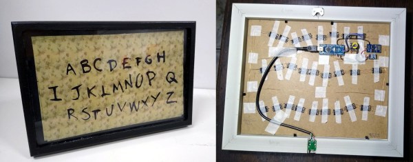
Word clock in the style of the Christmas lights from Stranger Things. If you know, you know.

Stranger Things Message Board Passes The Time By Spelling It Out

Will Netflix’s nostalgic hit Stranger Things be back for a fourth series anytime soon? We could pull out a Ouija board and ask the spirits, but we’d much rather ask closer to the source, i.e. a spirit in the upside down. And you know that the best way to do that is with LEDs — one for each letter of the alphabet so the spirit can spell out their messages.

Arduino, ESP01, and real-time clock powering this Stranger Things word clockAlthough contact with the Demogorgon’s world isn’t likely with [danjovic]’s open-source Stranger Things board, you are guaranteed to get the time spelled out for you every minute, as in, ‘it’s twenty-five (or six) to four’. And if you want to freak out your unwitting friends, you can covertly send messages to it from your phone.

There are two versions now — the original desktop version, and one that hangs on the wall and uses a high-quality photo print for the background. Both use an ESP-01 and an Arduino to help drive the 26 RGB LEDs, and use a DS2321 real-time clock for timing. We love the enameled wiring job on the wall-mount version, but the coolest part has to be dual language support for English and Brazilian Portuguese. You can check out demos of both after the break.

We’ve seen many a word clock around here, but this is probably one of the few that’s dripping with pop culture. If it’s stunning modernism you want, take a look at this painstakingly-constructed beauty.

Continue reading Stranger Things Message Board Passes The Time By Spelling It Out”

Pneumatic Can Crusher Awaits Your Command

A powerful robot awaiting for a verbal command to crush its foes might sound like something from a science fiction film, but now it’s a permanent fixture of the [Making Stuff] garage.  (Video, embedded below.) Thankfully this robot’s sworn enemy are aluminum cans, and the person controlling it with their voice isn’t a maniacal scientist, just a guy who’s serious about recycling. Well, we hope so anyway.

The star of the show is a heavy duty wall-mounted can crusher that [Making Stuff] built from some scrap steel and a pneumatic cylinder hooked up to the garage’s compressed air system. A solenoid operated valve allows an Arduino with attached ESP-01 to extend the cylinder whenever the appropriate command comes over the network. In this case, the goal was to tie the crusher into Google Assistant so a can would get smallified whenever one of Google’s listening devices heard the trigger phrase.

Note the ejector air line.

Obviously, those who’d rather keep Big Data out of their recycling bin don’t have to go down the same path. But that being said, having to give a specific voice command to activate the machine does provide a certain level of operational safety. At least compared to trusting some eBay sensor to tell the difference between an aluminum can and a fleshy appendage.

After crushing a few cans with his new toy, [Making Stuff] noticed a fairly troubling flaw in the design. Each time a can was crushed he had to reach into the maw of the machine to push its little flattened carcass out of the way. In other words, he was one bad line of code away from having one good hand.

The solution ended up being a new hose that runs from the exhaust port of the valve to the crushing chamber: once the cylinder retracts, the air exiting the valve pushes the crushed can out the rear of the machine and into a waiting pail underneath. Very slick.

Even if you’re not interested in the voice control aspect, this is a great design to base your own can crusher on. While it’s always a treat when a fully automatic crusher comes our way, we’ll admit the challenges of getting one to work reliably probably aren’t worth the hassle.

Continue reading “Pneumatic Can Crusher Awaits Your Command”

WiFive55: More Than A Smart 555 Replacement

“You could’ve done that with a 555 timer.” But what if all you have on hand is an ESP8266? [TechColab] needed to control a solenoid valve with a short pulse via a solid-state relay (SSR) but found that the trusty 555 timer was tricky to set properly. Additionally, they wanted to add features, such as fixed pulse length, that were difficult to implement—even with multiple timers. Still wanting to keep things cheap and accessible, [TechColab] has created the WiFive55, a 555 replacement based on the ESP-01 ESP8266 board.

[TechColab] began by investigating existing ESP-01 solid-state relay boards but found that many of them momentarily enable the output on startup—a risk [TechColab] deemed unacceptable. This was resolved in the WiFive55 by adding an RC filter to the SSR output, eliminating the output glitches at the cost of slowing switching time to around 20 ms—an acceptable trade for many SSR applications.

Since they were going to design a new PCB to support this improved ESP-01 SSR controller, [TechColab] decided to go all-out. To support loads of widely varying sizes, the PCB supports an optoisolator that switches up to 1 A, a MOSFET that switches up to 2 A, and an on-board relay or SSR that can switch up to 3 A. For heavy loads, it includes connections for an off-board SSR, which allow it to switch whatever current the SSR can handle (easily over 50 A). Because the ESP-01 is slightly more capable than the 555, the WiFive55 supports control via WiFi, GPIO, serial, and push-button. Keeping with the WiFive55’s original role as a 555 replacement, it even includes a header exposing a 555-like trigger and output interface!

We always like seeing inexpensive boards like the ESP-01 being used to their full potential, and we can’t wait to see what software [TechColab] cooks up for this! If you’re interested in getting started with the ESP-01, you might consider starting with this guide to blinking an LED over WiFi.

18650 Brings ESP8266 WiFi Repeater Along For The Ride

We’re truly fortunate to have so many incredible open source projects floating around on the Internet, since there’s almost always some prior art you can lean on. By combining bits and pieces from different projects, you can often save yourself a huge amount of time and effort. It’s just a matter of figuring out how all the pieces fit together, like in this clever mash-up by [bethiboothi] that takes advantage of the fact that the popular TP4056 lithium-ion battery charger module happens to be almost the exact same size of the ESP-01.

By taking a 3D printed design intended to attach a TP4056 module to the end of an 18650 cell and combining it with an ESP8266 firmware that turns the powerful microcontroller into a WiFi repeater, [bethiboothi] ended up with a portable network node that reportedly lasts up to three days on a charge. The observed range was good even with the built-in PCB antenna, but hacking on an external can get you out a little farther if you need it.

While it doesn’t appear that [bethiboothi] is using it currently, the esp_wifi_repeater firmware does have an automatic mesh mode which seems like it would be a fantastic fit for this design. Putting together an impromptu mesh WiFi network with a bunch of cheap battery powered nodes would be an excellent way to get network connectivity at an outdoor hacker camp, assuming the ESP’s CPU can keep up with the demand.

Oh Brother, Would You Look At This Cistercian Clock

We were beginning to think we’d seen it all when it comes to RGB clocks, but [andrei.erdei] found a fast path back into our hearts and minds. This clock is a digital representation of an ancient numeral system used by 13th century Cistercian monks before the Indo-Arabic system that we know and love today took over. It’s a compact system (at least for numbers 1-9,999) that produces numerals which sort of look like 16-segment displays gone crazy.

Image via Wikipedia

Every numeral has a line down the middle, and the system uses the four quadrants of space around it to display the ones, tens, hundreds, and thousands positions starting in the upper right corner.

[andrei] adapted the system to show time by assigning tens of hours to the thousands quadrant in the bottom left, hours to the hundreds quadrant in the bottom right, tens of minutes in the upper left, and minutes in the top right. The tricky part is that the system has no zero, but [andrei] just darkens the appropriate quadrant to represent zero.

The timekeeping is done with an ESP-01, and there are a total of 31 RGB LEDs including the middle bit, which blinks like a proper digital clock and doubles as a second hand. As usual, [andrei] has provided everything you’d need to build one of these for yourself. We admit that the system would take a little time to learn, but even if you never bothered to learn, this would make a nice conversation piece or focal point for sitting and staring. Take a minute to check it out in action after the break.

We love a good clock build no matter how it works. Sink your teeth into this clock that’s driven by a tuning fork.

Continue reading “Oh Brother, Would You Look At This Cistercian Clock”