The Anxiety Of Open Source: Why We Struggle With Putting It Out There

You’ve just finished your project. Well, not finished, but it works and you’ve solved all the problems worth solving, and you have a thing that works for you. Then you think about sharing your creation with the world. “This is cool” you think. “Other people might think it’s cool, too.” So you have to take pictures and video, and you wish you had documented some more of the assembly steps, and you have to do a writeup, and comment your code, and create a repository for it, maybe think about licensing. All of a sudden, the actual project was only the beginning, and now you’re stressing out about all the other things involved in telling other people about your project, because you know from past experience that there are a lot of haters out there who are going to tear it down unless it’s perfect, or even if it is, and even if people like it they are going to ask you for help or to make one for them, and now it’s 7 years later and people are STILL asking you for the source code for some quick little thing you did and threw up on YouTube when you were just out of college, and of course it won’t work anymore because that was on Windows XP when people still used Java.

Take a deep breath. We’ve all been there. This is an article about finding a good solution to sharing your work without dealing with the hassle. If you read the previous paragraph and finished with a heart rate twice what you started, you know the problem. You just want to share something with the world, but you don’t want to support that project for the rest of your life; you want to move on to new and better and more interesting projects. Here are some tips.

Continue reading “The Anxiety Of Open Source: Why We Struggle With Putting It Out There”

Robotic Arms Controlled By Your….. Feet?

The days of the third hand’s dominance of workshops the world over is soon coming to an end. For those moments when only a third hand is not enough, a fourth is there to save the day.

Dubbed MetaLimbs and developed by a team from the [Inami Hiyama Laboratory] at the University of Tokyo and the [Graduate School of Media Design] at Keio University, the device is designed to be worn while sitting — strapped to your back like a knapsack — but use while standing stationary is possible, if perhaps a little un-intuitive. Basic motion is controlled by the position of the leg — specifically, sensors attached to the foot and knee — and flexing one’s toes actuates the robotic hand’s fingers. There’s even some haptic feedback built-in to assist anyone who isn’t used to using their legs as arms.

The team touts the option of customizeable hands, though a soldering iron attachment may not be as precise as needed at this stage. Still, it would be nice to be able to chug your coffee without interrupting your work.

Continue reading “Robotic Arms Controlled By Your….. Feet?”

Recapture Radio’s Roots With An Updated Regenerative Receiver

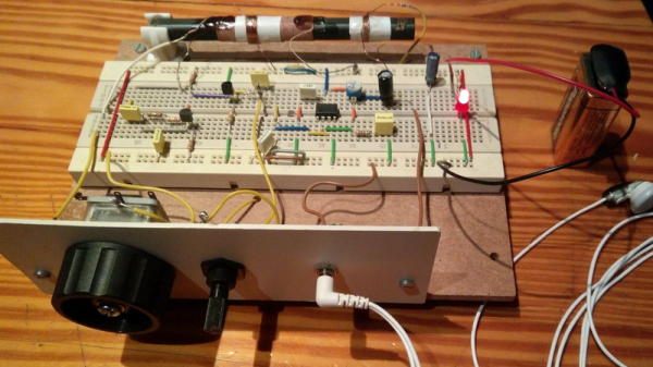
Crystal radios used to be the “gateway drug” into hobby electronics. Trouble was, there’s only so much one can hope to accomplish with a wire-wrapped oatmeal carton, a safety-pin, and a razor blade. Adding a few components and exploring the regenerative circuit can prove to be a little more engaging, and that’s where this simple breadboard regen radio comes in.

Sometimes it’s the simple concepts that can capture the imagination, and revisiting the classics is a great way to do it. Basically a reiteration of [Armstrong]’s original 1912 regenerative design, [VonAcht] uses silicon where glass was used, but the principle is the same. A little of the amplified RF signal is fed back into the tuned circuit through an additional coil on the ferrite rod that acts as the receiver’s antenna. Positive feedback amplifies the RF even more, a germanium diode envelope detector demodulates the signal, and the audio is passed to a simple op amp stage for driving a headphone.

Amenable to solderless breadboarding, or even literal breadboard construction using dead bug or Manhattan wiring, the circuit invites experimentation and looks like fun to fiddle with. And getting a handle on analog and RF concepts is always a treat.

[via r/electronics]

Derek Schulte: Path Planning For 3D Printers

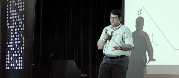
[Derek Schulte] designed and sells a consumer 3D printer, and that gives him a lot of insight into what makes them tick. His printer, the New Matter MOD-t, is different from the 3D printer that you’re using now in a few different ways. Most interestingly, it uses closed-loop feedback and DC motors instead of steppers, and it uses a fairly beefy 32-bit ARM processor instead of the glorified Arduino Uno that’s running many printers out there.

The first of these choices meant that [Derek] had to write his own motor control and path planning software, and the second means that he has the processing to back it up. In his talk, he goes into real detail about how they ended up with the path planning system they did, and exactly how it works. If you’ve ever thought hard about how a physical printhead, with momentum, makes the infinitely sharp corners that it’s being told to in the G-code, this talk is for you. (Spoiler: it doesn’t break the laws of physics, and navigating through the curve involves math.)

Continue reading “Derek Schulte: Path Planning For 3D Printers”

A Buck-Boost Converter From The Ground Up

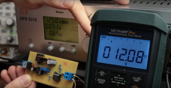
DC to DC conversion has come a long way. What was once took an electromechanical vibrator and transformer has been reduced to a PC board the size of a largish postage stamp that can be had for a couple of bucks on eBay. So why roll your own buck-boost converter for the ground up? Maybe because sometimes the best way to learn is by doing.

Continue reading “A Buck-Boost Converter From The Ground Up”

Building A Ball-Balancing Robot

robotBallBalance

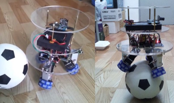
If you want a different kind of feedback systems challenge, ditch the Segway-style robots and build one that can balance on a ball. UFactory is a startup in Shenzhen, and this impressive little guy is a way of showing their skills applied to the classic inverted pendulum. At nearly 18 inches tall and weighing just over six pounds, the robot boasts a number of features beyond an accelerometer and gyroscope: it has both a WiFi module and a camera, and can be controlled via a homemade remote control or a Kinect.

The build uses plastic omni-directional wheels attached to 3 brushed dc motors, which attach to the base of the robot with custom-made aluminum brackets. The UFactory gang constructed the robot’s body out of three acrylic discs, which hold the electronics directly above the wheels. The brain seems to be an STM32 microcontroller that connects up to the motors and to the sensors.

You won’t find the code on their Instructable yet, but according to the comments they have plans to make the entire project open source. If you’re desperate for more details, the UFactory team seems willing to provide source code and other information via email. Make sure you see the video after the break, particularly the end where they demonstrate interference and carrying loads. This isn’t the first ball pendulum we’ve seen; take a trip down memory lane with the BallP ball balancing robot from 2010.

Continue reading “Building A Ball-Balancing Robot”