FPGA Powers Blazingly Fast LED Matrix Audio Visualizer

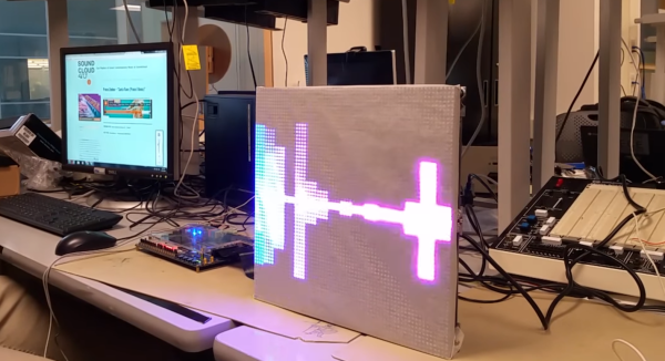
[Sam Miller], [Sahil Gupta], and [Mashrur Mohiuddin] worked together on a very fast LED matrix display for their final project in ECE 5760 at Cornell University.

Real time!
Real time!

They started, as any good engineering students, by finding a way to make their lives easier. [Sam] had built a 32×32 LED matrix for another class. So, they made three more and ended up with a larger and more impressive 64×64 LED display.

They claim their motivation was the love of music, but we have a suspicion that the true reason was the love all EEs share for unnaturally bright LEDs; just look at any appliance at night and try not be blinded.

The brains of the display is an Altera DE2-115 FPGA board. The code is all pure Verilog. The FFT and LED control are implemented in hardware on the FPGA; none of that Altera core stuff. To generate images and patterns they wrote a series of python scripts. But for us it’s the particle test shown in the video below that really turns our head. This system is capable of tracking and reacting to a lot of different elements on the fly why scanning the display at about 310 FPS. They have tested display scanning at twice that speed but some screen-wrap artifacts need to be worked out before that’s ready for prime time.

The team has promised to upload all the code to GitHub, but it will likely be a while before the success hangover blows over and they can approach the project again. You can view a video interview and samples of the visualizations in the videos after the break.

Thanks to their Professor, [Bruce Land], for submitting the tip! His students are always doing cool things. You can even watch some of his excellent courses online if you like: Here’s one on the AVR micro-controller.

Continue reading “FPGA Powers Blazingly Fast LED Matrix Audio Visualizer”

A Better Spectrum Analyzer For Your Rigol Scope

The Rigol DS1000 series of oscilloscopes are popular with hobbyists for good reason: they provide decent specs at a low price. However, their spectrum analysis abilities are lacking. While these scopes do have a Fast Fourier Transform (FFT) function, it’s limited and nearly useless for RF.

A FFT plotted by the PyDSA tool and a Rigol oscilloscope[Rich] wanted a spectrum analyzer for amateur radio purposes, but didn’t want to build his own sampling hardware for it. Instead, he wrote PyDSA, a software spectrum analyzer for Rigol DS1000 oscilloscopes. This tool uses the USB connection on the scope to fetch samples, and does the number crunching on a far more powerful PC. It’s able to plot a 16,000 point FFT at two sweeps per second when run on a decent computer.

PyDSA is a Python script that makes use of the Virtual Instrument Software Architecture (VISA) interface to control the scope and fetch the sample data. Fortunately there’s some Python libraries that take care of the protocol.

[Rich] is now able to use his scope to measure amateur radio signals, which makes a nice companion to his existing Teensy based SDR project. If you have a Rigol, you can grab the source on Github and try it out.

Visualizing The Fourier Transform

If you do any electronics work–especially digital signal processing–you probably know that any signal can be decomposed into a bunch of sine waves. Conversely, you can generate any signal by adding up a bunch of sine waves. For example, consider a square wave. A square wave of frequency F can be made with a sine wave of frequency F along with all of its odd harmonics (that is, 3F, 5F, 7F, etc.). Of course, to get a perfect square wave, you need an infinite number of odd harmonics, but in practice only a few will do the job.

Like a lot of abstract concepts, it is easy to understand the basic premise and you could look up any of the mathematical algorithms that can take a signal and perform a Fourier transform on it. But can you visualize why the transform works the way it does? If you can’t (or even if you can), you should check out [Mehmet’s] MATLAB visualization of harmonic circles. If you don’t have MATLAB yourself, you can always check out the video (see below).

Continue reading “Visualizing The Fourier Transform”

Spectrum Analyzer On The Cheap

Provided you have an NTSC-compatible TV you can build yourself a really inexpensive spectrum analyzer. From there you just need one trivial piece of hardware to complete this build. [Bruce Land] has come up with a spectrum analyzer that shouldn’t cost any more than $5, if that’s what’s been keeping you from adding this tool to your workbench!

The spectrum analyzer is based on a PIC32 microcontroller which was previously proven in his Oscilloscope project. [Bruce] has managed to squeeze quite a bit out of this robust chip; the spectrum analyzer has 450 kHz bandwidth and runs a 256 Hz TV display and can output over 30 updates per second. The microcontroller runs the Fast Fourier Transform (FFT) to do calculations, with great results.

[Bruce] notes that the project was based on TV framework from another project, and that the FFT was added on top of that. Be sure to check out the source code on the project site if you’ve been on the hunt for an inexpensive spectrum analyzer, and if you need something with more processing power but only slightly more money, check out the FFT that runs on the Raspberry Pi’s GPU.

Dirt Cheap Motor Balancing And Vibration Analysis

Ever the enterprising hacker and discerning tool aficionado, [Chris] knows the importance of “feel”. As a general rule, cheap tools will shake in your hand because the motors are not well-balanced. He wanted a way to quantify said feel on the cheap, and made a video describing how he was able to determine the damping of a drill using a few items most people have lying around: an earbud, a neodymium magnet, scrap steel, and Audacity.

He’s affixed the body of the drill to a cantilevered piece of scrap steel secured in a vise. The neodymium magnet stuck to the steel interrupts the magnetic field in the earbud, which is held in place with a third hand tool. [Chris] taped the drill’s trigger down and controls its speed a variac. First, [Chris] finds the natural frequency of the system using Audacity’s plot spectrum, and then gets the drill to run at the same speed to induce wobbling at different nodes. As he explains, one need not even use software to show the vibration nodes—a laser attached to the system and aimed at a phosphorescent target will plot the sine wave.

Just for fun, he severely unbalances the drill to find the frequencies at which the system will shake itself apart. Check it out after the break.

Continue reading “Dirt Cheap Motor Balancing And Vibration Analysis”

Is That A Tuner In Your Pocket…?

As a musician, it’s rare to consistently recognize with the naked ear whether or not a single instrument is in tune. There are a number of electronic devices on the market to aid in this, however if you’re leading into an impromptu performance to impress your friends, using one feels about as suave as putting on your dental headgear before bed. When tuning is necessary, why not do so in a fashion that won’t cramp your style?

To help his music-major friends add an element of Bond-like flare to the chore, [dbtayl] designed a chromatic tuner that’s disguised as a pocket watch, pet-named the “pokey”. The form for the custom casing was designed in OpenSCAD and cut from aluminum stock on a home-built CNC mill. Under its bass-clef bedecked cover is the PCB which was laid out in KiCad to fit the watch’s circular cavity, then milled from a piece of copped-clad board. The board contains the NXP Cortex M3 which acts as the tuner’s brain and runs an FFT (Fast Fourier Transform) that uses a microphone to match the dominant pitch it hears to the closest note. Five blue surface-mount LEDs on the side indicate how sharp or flat the note is, with the center being true.

[dbtayl’s] juxtaposition of circuitry in something that is so heavily associated with mechanical function is a clever play on our familiarity. You can see a test video of the trinket in action below:

Continue reading “Is That A Tuner In Your Pocket…?”

Easy And Effective Way To Measure PWM… Without A Scope!

Sometimes when a project is coming together, you need to cobble a tool together to get it completed. Whether it’s something very involved, like building a 3D printer to fabricate custom parts, or something relatively simple, like wiring a lightbulb and a battery together to create a simple continuity checker, we’ve all had to come up with something on the fly. Despite having access to an oscilloscope, [Brian] aka [schoolie] has come up with his own method for measuring PWM period and duty cycle without a scope, just in case there’s ever a PWM emergency!

The system he has come up with is so simple it’s borderline genius. The PWM signal in question is fed through a piezo speaker in parallel with a resistor. The output from the speaker is then sent to an FFT (fast fourier transform) app for Android devices, which produces a picture of a waveform. [schoolie] then opens the picture in MS Paint and uses the coordinates of the cursor and a little arithmetic to compute the period and the duty cycle.

For not using a scope, this method is pretty accurate, and only uses two discrete circuit components (the resistor and the speaker). If you’re ever in a pinch with PWM, this is sure to help, and be a whole lot cheaper than finding an oscilloscope!