It’s easy to get caught up in the excitement of creation as we’re building our latest widget. By the same token, it’s sometimes difficult to fully appreciate just how old some of the circuits we use are. Even the simplest of projects might make use of elements that were once a mess on some physicist’s or engineer’s lab bench, with components screwed to literal breadboards and power supplied by banks of wet-cell batteries.
One such circuit turns 100 years old in June, which is surprising because it literally is the building block of every computer. It’s the flip-flop, and while its inventors likely couldn’t have imagined what they were starting, their innovation became the basic storage system for the ones and zeros of the digital age.
A flip-flop is one of the most basic digital electronic circuits. It can most easily be built from just two transistors, although they can and have been built out of vacuum tubes, NAND and NOR gates, and Minecraft redstone. Conventional wisdom says you can’t build a flip-flop with just one transistor, but here we are. [roelh] has built a flip-flop circuit using only one transistor and some bizarre logic that’s been slowly developing over on hackaday.io.
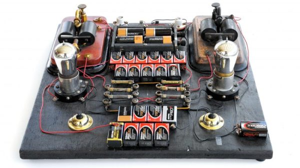
[roelh]’s single transistor flip-flop is heavily inspired by a few of the strange logic projects we’ve seen over the years. The weirdest, by far, is [Ted Yapo]’s Diode Clock, a digital clock made with diode-diode logic. This is the large-scale proof of concept for the unique family of logic circuits [Ted] came up with that only uses bog-standard diodes to construct arbitrary digital logic.
The single-transistor flip-flop works just like any other flip-flop — there are set and reset pulses, and a feedback loop to keep the whatever state the output is in alive. The key difference here is the addition of a clock signal. This clock, along with a few capacitors and a pair of diodes, give this single transistor the ability to store a single bit of information, just like any other flip-flop.
This is, without a doubt, a really, really weird circuit but falls well into territory that is easily understood despite being completely unfamiliar. The key question here is, ‘why?’. [roelh] says this could be used for homebrew CPUs, although this circuit is trading two transistors for a single transistor, two diodes, and a few more support components. For vacuum tube-based computation, this could be a very interesting idea that someone at IBM in the 40s had, then forgot to write down. Either way, it’s a clever application of diodes and an amazing expression of the creativity that can be found on a breadboard.
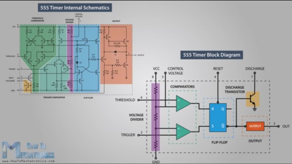
One way to understand how the 555 timer works and how to use it is by learning what the pins mean and what to connect to them. A far more enjoyable, and arguably a more useful way to learn is by looking at what’s going on inside during each of its modes of operation. [Dejan Nedelkovski] has put together just such a video where he walks through how the 555 timer IC works from the inside.
We especially like how he immediately removes the fear factor by first showing a schematic with all the individual components but then grouping them into what they make up: two comparators, a voltage divider, a flip-flop, a discharge transistor, and an output stage. Having lifted the internals to a higher level, he then walks through examples, with external components attached, for each of the three operating modes: bistable, monostable and astable. If you’re already familiar with the 555 then you’ll enjoy the trip down memory lane. If you’re not familiar with it, then you soon will be. Check out his video below.
Gisselquist Technology recently posted a good blog article about metastability and common solutions. If you are trying to learn FPGAs, you’ll want to read it. If you know a lot about FPGAs already, you might still pick up some interesting tidbits in the post.
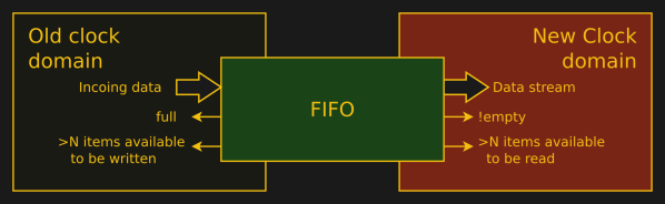
Don’t let the word metastability scare you. It is just a fancy way of saying that a flip flop can go crazy if the inputs are not stable for a certain amount of time before the clock edge and remain stable for a certain amount of time after the clock edge. These times are the setup and hold times, respectively.
Normally, your design tool will warn you about possible problems if you are using a single clock. However, any time your design generates a signal with one clock and then uses it somewhere with another clock, metastability is a possible problem. Even if you only have one clock, any inputs from the outside world that don’t reference your clock — or, perhaps, any clock at all — introduce the possibility of metastability. Continue reading “FPGA Metastability Solutions”→
[Scott] had a simple problem – he was tired of leaning over his work bench to change the volume on his speakers. He desired a system that would readily allow him to switch the speakers on and off from a more comfortable distance. Not one to settle for the more conventional solutions available, [Scott] whipped up a RADAR-activated switch for his speaker system.
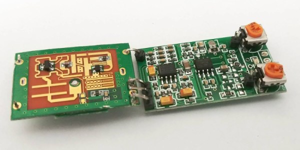
The build relies on a surprisingly cost-effective RADAR module available off the shelf, running in the 5.8GHz spectrum. At under $10, it’s no big deal to throw one of these into a project that requires some basic distance sensing. [Scott] decided to keep things simple – instead of going with a full-fat microcontroller to control the speakers, a 74HC590 IC was used to create a latch. Each time the RADAR module senses an object in close proximity, it toggles the state of the latch. The latch then controls a transistor that switches the power for the speakers.
As useful as computers are, most of them have all the design charm of a rubber doorstop. Oh, for the heady early days of computing, when vacuum tubes ruled, hardware was assembled by hand, and engineers always wore a tie.
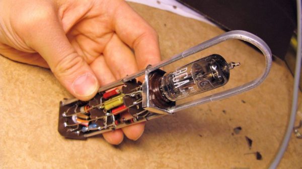
Looking to recreate an elegant bit of computing hardware from that more civilized age, [updatebjarni] built a reproduction of a 1948 IBM TR-2 flip-flop module — 1,250 of which once formed the memory of the IBM Model 604 Calculating Punch. Admittedly more of a high-speed adding machine than a computer, the 604 is still an important piece of computing history, and [updatebjarni]’s scrap-bin reproduction of the field-replaceable module served as part of a computer history exhibit.
With a single 6J6 double triode tube nestled inside a bent aluminum frame, the goal was to reproduce the appearance of the original TR-2 module, and so the passive components wired up point-to-point style below the tube socket were chosen for their vintage look. That’s not to say the flip-flop won’t function. Although [updatebjarni] hasn’t tested it, he’s built other functional flip-flops from vintage components before, so this one should work too. Only 1,249 left to build and he’ll have enough for a working 604.
If you like this kind of build, you should probably check out some of our Vintage Computer Festival coverage. VCF East in April was a huge success, and VCF West is coming up in August in Mountain View. Hackaday will be well represented there, so stop by.
When I first got interested in computers, it was all but impossible for an individual to own a computer outright. Even a “small” machine cost a fortune not to mention requiring specialized power, cooling, and maintenance. Then there started to be some rumblings of home computers (like the Mark 8 we recently saw a replica of) and the Altair 8800 burst on the scene. By today’s standards, these are hardly computers. Even an 8-bit Arduino can outperform these old machines.
As much disparity as there is between an Altair 8800 and a modern personal computer, looking even further back is fascinating. The differences between the original computers from the 1940s and anything even remotely “modern” like an Altair or a PC are astounding. If you are interested in that kind of history, you should read a paper entitled “Electronic Computing Circuits of the ENIAC” by [Arthur W. Burks].
These mid-century designers used tubes and were blazing new ground. Part of what makes the ENIAC so different is that it had a different design principle than a modern computer. It was less a general purpose stored-program computer and more of a collection of logic circuits that could be configured to solve problems — sort of a giant vacuum tube FPGA, if you will. It used some internal representations that proved to be suboptimal which also makes it seem strange. The EDSAC — a later device — was closer to what we think of as a computer. Yet the ENIAC was a major step in the direction of a practical digital computer.
Cost and Size
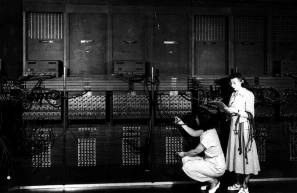
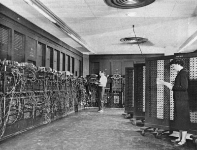
Programming the ENIAC in 1951 (±4 years) [Image Source: Public Domain]The size of ENIAC is hard to imagine. The device had about 18,000 tubes, 7,000 diodes, 70,000 resistors, 10,000 capacitors, and 6,000 switches. There were 5 million hand-soldered joints! ([Thomas Haigh] tells us that while this is widely reported, the real number was about 500,000.) Physically, it stood 10 feet tall, 3 feet deep, and 100 feet long. The tube filaments alone required 80 kW of power. Even the cooling system consumed 20 kW. In total, it took 150 kW to run the beast.
The cost of the machine was about $487,000. Almost a half-million dollars in 1946 is plenty. But that’s nearly seven million dollars in today’s money. What was worth that kind of expenditure? The military built firing tables for shell trajectories. From the [Burks] paper:
“A skilled computer with a desk machine can compute a 60-second trajectory in about twenty hours…”
Keep in mind that in 1946, a computer was a person. [Burks] goes on to say that a differential analyzer can do the same job in 15 minutes. ENIAC, on the other hand, could do it in 30 seconds and with a greater precision than the differential analyzer.