Matrix Of Resistors Forms The Hot Hands Behind This Thermochromic Analog Clock

If you’re going to ditch work, you might as well go big. A 1,024-pixel thermochromic analog clock is probably on the high side of what most people would try, but apparently [Daniel Valuch] really didn’t want to go to work that day.

The idea here is simple: heat up a resistor by putting some current through it, lay a bit of thermochromic film over it, and you’ve got one pixel. The next part was not so simple: expanding that single pixel to a 32 by 32 matrix.

To make each pixel square-ish, [Daniel] chose to pair up the 220-ohm SMD resistors for a whopping 2,048 components. Adding to the complexity was the choice to drive them with a 1,024-bit shift register made from discrete 74LVC1G175 flip flops. With the Arduino Nano and all the other support components, that’s over 3,000 devices with the potential to draw 50 amps, were someone to be foolish or unlucky enough to turn on every pixel at once. Luckily, [Daniel] chose to emulate an analog clock here; that led to additional problems, like dealing with cool-down lag in the thermochromic film when animating the hands, which had to be dealt with in software.

We’ve seen other thermochromic displays before, including recently with this temperature and humidity display. This one may not be the highest resolution display out there, but it’s big and bold and slightly dangerous, and that makes it a win in our book.

3D Print Your Very Own Mechanical Computer

Most Hackaday readers are familiar with computers from the 70s and 80s, but what about ones even older than that? The Digi Comp 1 was a commercially available computer from the 1960s that actually cost less than a modern-day microcontroller. The catch? It was mechanical rather than electrical. Thanks to retro-wizard [Mike Gardi], now anyone can build a replica of one.

Admittedly the Digi Comp 1 was more of a toy than a tool, but it was still a working computer. It contained three flip-flops (memory) and had a lever that acted as a clock, allowing the user to perform boolean operations and some addition and subtraction. Certainly not advanced, but interesting nonetheless. [Mike]’s version of the Digi Comp 1 has an extra bit when compared to the original and includes some other upgrades, but largely remains faithful to the original design.

If you want to print one of these on your own, [Mike] has made all of the files available on Thingiverse. He has also experimented with other mechanical computers as well, including the sequel Digi Comp 2. We’ve seen some recent interest in that mechanical computer lately as well.

Continue reading “3D Print Your Very Own Mechanical Computer”

Circuit VR: Redundant Flip Flops And Voting Logic

We are somewhat spoiled because electronics today are very reliable compared to even a few decades ago. Most modern electronics obey the bathtub curve. If they don’t fail right away, they won’t fail for a very long time, in all likelihood. However, there are a few cases where that’s not a good enough answer. One is when something really important is at stake — the control systems of an airplane, for example. The other is when you are in an environment that might cause failures. In those cases — near a nuclear reactor or space, for example, you often are actually dealing with both problems. In this installment of Circuit VR, I’ll show you a few common ways to make digital logic circuits more robust with some examples you can run in the Falstad simulator in your browser.

Continue reading “Circuit VR: Redundant Flip Flops And Voting Logic”

Juggling Machine Listens To The Bounce To Keep Ball In The Air

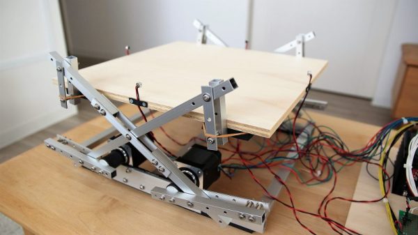
It’s a seemingly simple task: bounce a ping-pong ball on a wooden paddle. So simple that almost anyone can pick up a ball and a paddle and make a reasonable job of it. Now, close your eyes and try to do it just by the sound the ball makes when it hits the paddle. That’s a little tougher, but this stepper-driven platform juggler manages it with aplomb.

That’s not to say that the path to the finished product in the video below was a smooth one for [tkuhn]. He went through multiple iterations over the last two years, including a version that surrounded the juggling platform with a fence of phototransistors to track where the ball was at any time. That drove four stepper motors through a cross-linkage that popped the platform up at just the right moment to keep the ball moving, and at just the right angle to nudge it back toward the center of the platform. The current version of the platform does away with the optical sensors in favor of four small microphones. The mics pick up the sharp, well-defined sound of the ball hitting the platform, process the signal through an analog circuit, and use that signal to trigger a flip-flop if the signal exceeds a setpoint. An Arduino then measures the time delay between arriving signals, calculates the ball’s position on the platform, and drives the steppers through a PID loop to issue the corrective bounce.

The video below is entrancing, but we found ourselves wishing for a side view of the action too. It’s an impressive build nonetheless, one that reminds us of the many maze-runner and Stewart platform robots we’ve seen.

Continue reading “Juggling Machine Listens To The Bounce To Keep Ball In The Air”

A 100th Birthday Celebration For The Flip Flop

It’s easy to get caught up in the excitement of creation as we’re building our latest widget. By the same token, it’s sometimes difficult to fully appreciate just how old some of the circuits we use are. Even the simplest of projects might make use of elements that were once a mess on some physicist’s or engineer’s lab bench, with components screwed to literal breadboards and power supplied by banks of wet-cell batteries.

One such circuit turns 100 years old in June, which is surprising because it literally is the building block of every computer. It’s the flip-flop, and while its inventors likely couldn’t have imagined what they were starting, their innovation became the basic storage system for the ones and zeros of the digital age.

Continue reading “A 100th Birthday Celebration For The Flip Flop”

The One-Transistor Flip-Flop

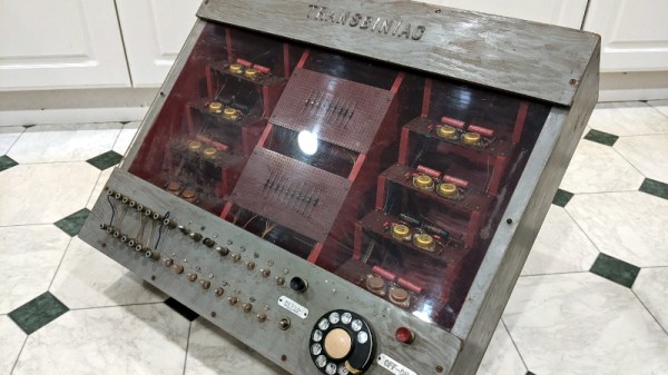
A flip-flop is one of the most basic digital electronic circuits. It can most easily be built from just two transistors, although they can and have been built out of vacuum tubes, NAND and NOR gates, and Minecraft redstone. Conventional wisdom says you can’t build a flip-flop with just one transistor, but here we are. [roelh] has built a flip-flop circuit using only one transistor and some bizarre logic that’s been slowly developing over on hackaday.io.

[roelh]’s single transistor flip-flop is heavily inspired by a few of the strange logic projects we’ve seen over the years. The weirdest, by far, is [Ted Yapo]’s Diode Clock, a digital clock made with diode-diode logic. This is the large-scale proof of concept for the unique family of logic circuits [Ted] came up with that only uses bog-standard diodes to construct arbitrary digital logic.

The single-transistor flip-flop works just like any other flip-flop — there are set and reset pulses, and a feedback loop to keep the whatever state the output is in alive. The key difference here is the addition of a clock signal. This clock, along with a few capacitors and a pair of diodes, give this single transistor the ability to store a single bit of information, just like any other flip-flop.

This is, without a doubt, a really, really weird circuit but falls well into territory that is easily understood despite being completely unfamiliar. The key question here is, ‘why?’. [roelh] says this could be used for homebrew CPUs, although this circuit is trading two transistors for a single transistor, two diodes, and a few more support components. For vacuum tube-based computation, this could be a very interesting idea that someone at IBM in the 40s had, then forgot to write down. Either way, it’s a clever application of diodes and an amazing expression of the creativity that can be found on a breadboard.

How the 555 timer IC works

Learning The 555 From The Inside

One way to understand how the 555 timer works and how to use it is by learning what the pins mean and what to connect to them. A far more enjoyable, and arguably a more useful way to learn is by looking at what’s going on inside during each of its modes of operation. [Dejan Nedelkovski] has put together just such a video where he walks through how the 555 timer IC works from the inside.

We especially like how he immediately removes the fear factor by first showing a schematic with all the individual components but then grouping them into what they make up: two comparators, a voltage divider, a flip-flop, a discharge transistor, and an output stage. Having lifted the internals to a higher level, he then walks through examples, with external components attached, for each of the three operating modes: bistable, monostable and astable. If you’re already familiar with the 555 then you’ll enjoy the trip down memory lane. If you’re not familiar with it, then you soon will be. Check out his video below.

Continue reading “Learning The 555 From The Inside”