Hey, MiSTer Emulator, Gimme Almost Any Classic Platform!

I’m back with another of the talks from Hackerspace Gent’s NewLine conference, fresh from my weekend of indulgence quaffing fine Belgian food and beers while mixing with that country’s hacker community. This time it’s an overview from [Michael Smith] of the MiSTer project, a multi-emulator using an FPGA to swap out implementations of everything from an early PDP minicomputer to an 80486SX PC.

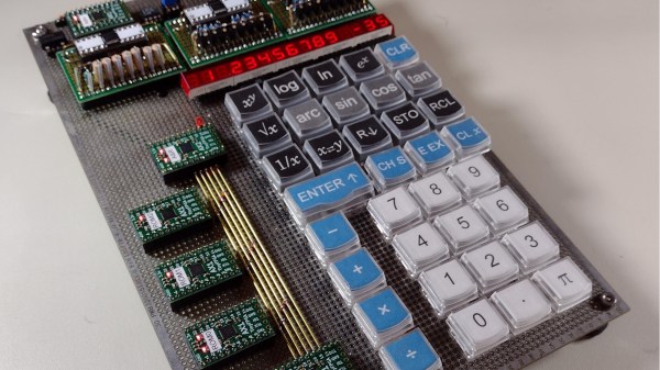
At its heart is a dev board containing an Intel Cyclone SoC/FPGA, to which a USB hub must be added, and then a memory upgrade to run all but the simplest of cores. Once the hardware has been taken care of it almost seems as though there are no classic platforms for which there isn’t a core, as a quick browse of the MiSTer forum attests. We are treated to seamless switching between SNES and NED platforms, and even switching different SID chip versions during a running Commodore 64 demo.

There are many different routes to a decent emulator set-up be they using hardware, software, or a combination of both. It’s unlikely that there are any as versatile as this one though, and we’re guessing that as it further evolves it will become a fixture below the monitor or TV of any gamer.  It’s a step up from single-platform FPGA emulators, that’s for certain!

Continue reading “Hey, MiSTer Emulator, Gimme Almost Any Classic Platform!”

DIY LED Cube For The Masses

No matter what the size or shape of an LED, it brings out the curiosity in every hardware nerd, and is the lifeblood of badge life around the planet. Then there is the LED cube that takes LEDs to all sides — literally. [Tomverbeure] had his own adventure of creating an LED Cube by piecing together Pixel Purses and a Cisco3G Modem.

A quick search for Pixel Purse on the internet reveals a toy lady’s handbag with an LED matrix embedded in one side. [tomverbeure] tore down 12 of these so as to get two panels for each side of his creation. After a little bit of experimenting with PCB corner brackets, he finally got it right and he is able to merge the pieces together to form the cube.

Next comes the brain and the elected device An FPGA from an HWIC-3G-CDMA modem. Cisco routers have extension slots and the HWIC connector on this particular piece had usable GPIOs that connect directly to the Altera FPGA. Inside the FPGA, a RISC-V soft CPU is used to generate images that get processed and dispatched in a hardware block. [Tomverbeure] does a detailed explanation of the implementation for all the blocks which were written in SpinalHDL. The video below shows the project in action.

We love the detail that [Tomverbeure] provides and hope it does not drive up the prices of the pixel purse too much. If you are looking for a more fine pitched cube, look no further than this one. If you end up making your own, be sure to send us a link.

Traditional Analogue And An FPGA Make This Junkbox HF Receiver A Bit Special

We will have all at some point seen a fascinating project online, only to find not enough information to really appreciate and understand it. Such a project came [Bill Meara]’s way over at the SolderSmoke podcast, and he was fortunately able to glean more from its creator. What [Tom] had made from junkbox parts was a fairly traditional analogue receiver for the 20m amateur band which would be quite an achievement in itself, but what makes it special is its use of an FPGA to augment the analogue tuning.

A traditional analogue radio has a local oscillator which is mixed with the signal from the antenna, and an intermediate frequency of the difference between oscillator and desired signal is filtered from the result and amplified. The oscillator on older receivers would have used a free running tuned circuit, while a newer device might use a phase-locked loop to derive a stable frequency from a crystal.

What [Tom]’s receiver does is take a free-running traditional receiver and use the FPGA as a helper. It has a frequency meter that drives the display, but it also uses the measured figure to adjust the oscillator and keep it on frequency. It has two modes; while tuning it’s a traditional analogue receiver, but when left alone the FPGA stops it drifting. We like it, it’s definitely a special project.

We’ve featured a lot of radio receivers over the years, and this certainly isn’t the only one that’s a bit unconventional.

Raspberry Pi Real-Time HAT

New Part Day: Raspberry Pi HAT For IEEE1588 Precision Time Protocol

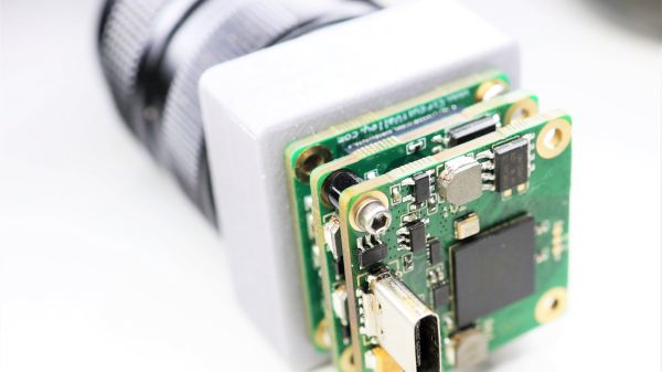
The new Real-Time HAT by InnoRoute adds IEEE1588 PTP support in hardware to a Raspberry Pi 4 nestled beneath. Based around a Xilinx Artix-7 FPGA and a handful of gigabit Ethernet PHY devices, the HAT acts as network-passthrough, adding accurate time-stamps to egress (outgoing) packets and stripping time-stamps from the ingress (incoming) side.

This hardware time-stamping involves re-writing Ethernet packets on-the-fly using specialised network hardware which the Raspberry Pi does not have. Yes, there are software-only 1588 stacks, but they can only get down to 10s of microsecond resolutions, unlike a hardware approach which can get down to 10s of nanoseconds.

1588 is used heavily for applications such as telecoms infrastructure, factory equipment control and anything requiring synchronisation of data-consuming or data-producing devices. CERN makes very heavy use of 1588 for its enormous arrays of sensors and control equipment, for all the LHC experiments. This is the WhiteRabbit System, presumably named after the time-obsessed white rabbit of Alice In Wonderland fame. So, if you have a large installation and a need for precisely controlling when stuff happens across it, this may be just the thing you’re looking for.

IEEE1588 PTP Synchronisation

The PTP client and master device ping a few messages back and forth between themselves, with the network time-stamper recording the precise moment a packet crosses the interface. These time-stamps are recorded with the local clock. This is important. From these measurements, the time-of-flight of the packet and offset of the local clock from the remote clock may be calculated and corrected for. In this way each client node (the hat) in the network will have the same idea of current time, and hence all network packets flowing through the whole network can be synchronised.

The beauty of the system is that the network switches, wiring and all that common infrastructure don’t need to speak 1588 nor have any other special features, they just need to pass along the packets, ideally with a consistent delay.

The Real-Time HAT configures its FPGA via SPI, straight from Raspberry Pi OS, with multiple applications possible, just by a change on the command line. It is possible to upload custom bitstreams, allowing the HAT to be used as a general purpose FPGA dev board should you wish to do so. It even stacks with the official PoE HAT, which makes it even more useful for hanging sensors on the end of a single wire.

Of course, if your needs are somewhat simpler and smaller in scale than a Swiss city, you could just hack a GPS clock source into a Raspberry Pi with a little soldering and call it a day.

Robot Pet Is A Chip Off The Old Logic Block

When [Ezra Thomas] needed inspiration for his senior design project, he only needed to look as far as his own robot. Built during his high school years from the classic 1979 Frank DaCosta book “How to Build Your Own Working Robot Pet”, [Ezra] had learned the hard way the many limitations and complexities of the wire wrapped 74xx series logic chips surrounding its 8085 processor.

[Ezra] embarked on a quest to recreate the monstrosity in miniature, calling it Pet on a Chip. Using a modern FPGA chip allows the electronics to shrink by an order of magnitude and provides flexibility for future expansion. Implementing an 8 bit CPU on the amply sized FPGA left plenty of room for a VGA GPU, motor controller, serial UART, and more. Programming the CPU is handled by a custom assembler written in Python.

The results? Twelve times less weight, thirteen times less power draw, better performance, and a lot of room for growth. [Ezra] hints at an I2C bus expansion as well as a higher level programming language to make software development less of a hurdle.

The Pet On A Chip is a wonderfully engineered project and we hope that we’ll be seeing more such from [Ezra] as time goes by. Watch his Pet On A Chip in action in the video below the break.

If [Ezra]’s FPGA escapades have you wondering how to get started, you can check out this introduction to FPGA from the 2019 Hackaday Superconference. And if you have your own FPGA creation to share, please let us know via the Tip Line!

Continue reading “Robot Pet Is A Chip Off The Old Logic Block”

Accurate Digital Clock Keeps Ticking With FPGA

Even the most punctual among us are content to synchronize their clocks to external time sources like navigation satellite constellations, network time servers, frequency-controlled AC mains, or signals broadcast by radio stations such as WWV, CHU, and DFC77 — but not [zaphod]. After building a couple of more traditional clocks over the years, he set his sights on making a completely isolated digital clock that doesn’t rely on external synchronization (well, except to initialize the time at first power-up).

The accuracy goal he set for himself was that of a Casio F-91W wristwatch, which is specified to maintain +/- 30 seconds per month (about 12 ppm). At the heart of the design is an oven-controlled crystal oscillator whose stability is in the single-digits parts-per-billion.

The counter chain that accumulates the time is implemented in an FPGA — admittedly overkill, but [zaphod] wanted to learn FPGA programming for this project as well. An ATmega328 drives the display and does other bookkeeping tasks. The whole design is partitioned into three PCBs which fit inside a custom 3D-printed case.

[zaphod] does a thorough job documenting his build, including the bugs and failures along the way. We like the honest summary he wrote at the project’s conclusion, noting things that could be improved or should have been done differently. Be sure to check out the GitHub repository, where all the source code and PCB design files are posted. How accurate is your wristwatch, if you even wear one anymore?

Custom RISC-V Processor Built In VHDL

While ARM continues to make inroads into the personal computing market against traditional chip makers like Intel and AMD, it’s not a perfect architecture and does have some disadvantages. While it’s a great step on the road to software and hardware freedom, it’s not completely free as it requires a license to build. There is one completely open-source and free architecture though, known as RISC-V, and its design and philosophy allow anyone to build and experiment with it, like this build which implements a RISC-V processor in VHDL.

Since the processor is built in VHDL, a language which allows the design and simulation of integrated circuits, it is possible to download the code for the processor and then program it into virtually any FPGA. The processor itself, called NEORV32, is designed as a system-on-chip complete with GPIO capabilities and of course the full RISC-V processor implementation. The project’s creator, [Stephan], also struggled when first learning about RISC-V so he went to great lengths to make sure that this project is fully documented, easy to set up, and that it would work out-of-the-box.

Of course, since it’s completely open-source and requires no pesky licensing agreements like an ARM platform might, it is capable of being easily modified or augmented in any way that one might need. All of the code and documentation is available on the project’s GitHub page. This is the real benefit of fully open-source hardware (or software) which we can all get behind, even if there are still limited options available for RISC-V personal computers for the time being.

How does this compare to VexRISC or PicoSOC? We don’t know yet, but we’re always psyched to have choices.