Blockchain has existed as a concept since the early 1990s, but keeping a distributed ledger for IoT transactions wasn’t widely implemented until IOTA developed Tangle. The blockchain company was initially founded as a hardware startup and pivoted to work on transactional settlement for IoT. The Tangle, their distributed ledger architecture based on a directed acyclic graph (DAG) works as a “blockchain without the blocks and the chain”.
As its name implies, the Tangle is a web of transactions that references its past two transactions and a subsection of other transactions. Rather than miners and stakers being responsible for overall consensus, all active participants are involved in the approval of transactions. The transaction process requires the client to sign with their private keys, select two random unconfirmed transactions to be referenced, and perform proof-of-work.
The proof-of-work has an unfortunately high difficulty as you might expect. The process is similar to finding a nonce in Bitcoin mining, although the difficulty is set at a lower threshold due to the transactions running on lower-power nodes. Even so, since IOTA transactions commonly occur on small embedded platforms this can take several minutes to complete, a relatively long time considering these are mere transactions.
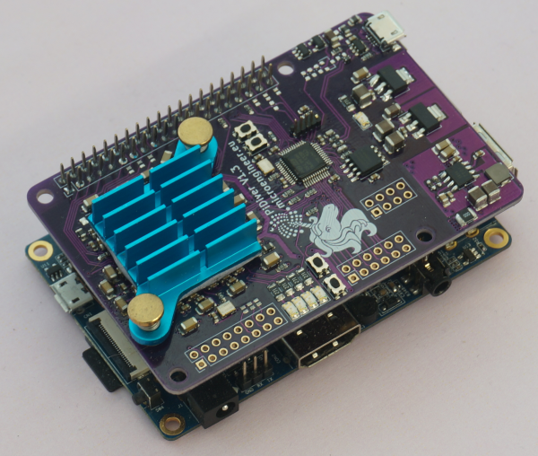
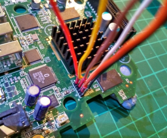
Since Curl-P81 hashes should be computed in parallel, they can’t be computed efficiently on general purpose CPUs. The PiDiver 1.3, [Thomas Pototschnig]’s port of the IOTA Reference Implementation (IRI) PearlDiver, performs searches for nonces. Because it runs on FPGAs, it is able to speed up the proof-of-work by a factor of more than 140 when compared to a Raspberry Pi. The FPGA is able to calculate one round of the hash in a single clock cycle, and a complete hash in 85 cycles (as well as testing for a valid nonce). Seven parallel hashes can be calculated at once, giving 15.8MHash/s at a frequency of 188MHz. The proof-of-work takes ~300ms on the FPGA when compared to 90s on a Raspberry Pi, so this is a significant improvement in speed.
Since the project is open source, the core can be used by IRI for creating a modified version of their PearlDiver. The board can be used as a Raspberry Pi HAT, although it can also be connected via USB to work without the Pi.
While this doesn’t address the security concerns of using IOTA with personal IoT devices, it is certainly a significant improvement on the speed of their proof-of-work process, and the software speedup is incredibly satisfying to watch.
Continue reading “Speeding Up IOTA Proof Of Work Using FPGAs” →