Resin-Printed Gears Versus PLA: Which Is Tougher?

When it comes to making gearboxes, 3D printing has the benefit that it lets you whip up whatever strange gears you might need without a whole lot of hunting around at obscure gear suppliers. This is particularly good for those outside the limited radius served by McMaster Carr. When it came to 3D printed gears though, [Michael Rechtin] wondered whether PLA or resin-printed gears performed better, and decided to investigate.

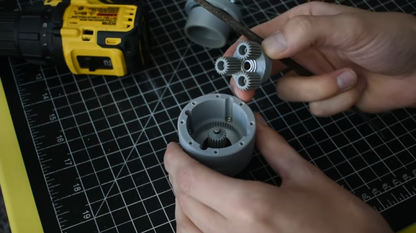
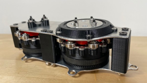
The subject of the test is a 3D-printed compound planetary gearbox, designed for a NEMA-17 motor with an 80:1 reduction. The FDM printer was a Creality CR10S, while the Creality LD02-H was on resin duty.

The assembled gearboxes were tested by using a 100 mm arm to press against a 20 kg load cell so that their performance could be measured accurately. By multiplying the force applied to the load cell by theĀ  length of the arm, the torque output from the gearbox can be calculated. A rig was set up with each gearbox pushing on the load cell in turn, with a closed-loop controller ensuring the gearbox is loaded up to the stall torque of the stepper motor before letting the other motor take over.

Continue reading “Resin-Printed Gears Versus PLA: Which Is Tougher?”

Do You Need A Cycloidal Drive?

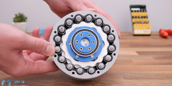
A cycloidal gear drive is one of the most mesmerizing reduction gears to watch when it is running, but it’s not all just eye-candy. Cycloidals give decent gearing, are relatively compact and back-drivable, and have low backlash and high efficiency. You probably want one in the shoulder of your robot arm, for instance.

But designing and building one isn’t exactly straightforward. Thanks, then, to [How To Mechatronics] for the lovely explanation of how it works in detail, and a nice walkthrough of designing and building a cycloidal gear reducer out of 3D printed parts and a ton of bearings. If you just want to watch it go, check out the video embedded below.

The video is partly an ad for SolidWorks, and spends a lot of time on the mechanics of designing the parts for 3D printing using that software. Still, if you’re using any other graphical CAD tool, you should be able to translate what you learned.

It’s amazing that 3D printing has made sophisticated gearbox designs like this possible to fabricate at home. This stuff used to be confined to the high-end machine shops of fancy robotics firms, and now you can make one yourself this weekend. Not exotic or unreliable enough for you? Well, then, buy yourself some flexible filament and step on up to the strain wave, aka “harmonic drive”, gearbox.

Thanks to serial tipster [Keith] for the tip!

Continue reading “Do You Need A Cycloidal Drive?”

Inconsistent layer heights in a 3D print

An Easy Fix For Inconsistent Layers In Cheap 3D Printers

If there’s one thing you can say about [Stefan] from CNC Kitchen, it’s that he’s methodical when he’s working on an improvement to his 3D printing processes, or when he’s chasing down a problem with a printer. Case in point: this root-cause analysis of extrusion inconsistencies with an entry-level 3D printer.

The printer in question is a Cetus MK3, a printer that found its way onto many benches due to its ridiculously low price and high-quality linear bearings. Unfortunately, there’s still a lot to be desired about the printer, and its tendency for inconsistent layers was chief among [Stefan]’s gripes. Such “blubbiness” can be pinned on any number of problems, but rather than guess, [Stefan] went through a systematic process of elimination to find the root cause. We won’t spoil the ending, but suffice it to say that the problem was subtle, and could probably be the cause of similar problems with other printers. The fix was also easy, and completely mechanical — just a couple of parts to replace. The video below shows the whole diagnosis process, as well as the before and after comparisons. [Stefan] also teases an upcoming treatment on how he converted the Cetus from the stock proprietary control board, which we’re interested in seeing.

If you haven’t checked out any of [Stefan]’s other 3D printing videos, you really should take a look. Whether it’s vibration damping with a concrete paver, salt annealing prints for strength, or using finite element analysis to optimize infills, he’s always got an interesting take on 3D printing.

Continue reading “An Easy Fix For Inconsistent Layers In Cheap 3D Printers”

Differential Drive Doesn’t Quite Work As Expected

Placing two motors together in a shared drive is a simple enough task. By using something like a chain or a belt to couple them, or even placing them on the same shaft, the torque can be effectively doubled without too much hassle. But finding a way to keep the torque the same while adding the speeds of the motors, rather than the torques, is a little bit more complicated. [Levi Janssen] takes us through his prototype gearbox that attempts to do just that, although not everything works exactly as he predicts.

The prototype is based on the same principles as a differential, but reverses the direction of power flow. In something like a car, a single input from a driveshaft is sent to two output shafts that can vary in speed. In this differential drive, two input shafts at varying speeds drive a single output shaft that has a speed that is the sum of the two input speeds. Not only would this allow for higher output speeds than either of the two motors but in theory it could allow for arbitrarily fine speed control by spinning the two motors in opposite directions.

The first design uses two BLDC motors coupled to their own cycloidal drives. Each motor is placed in a housing which can rotate, and the housings are coupled to each other with a belt. This allows the secondary motor to spin the housing of the primary motor without impacting the actual speed that the primary motor is spinning. It’s all a lot to take in, but watching the video once (or twice) definitely helps to wrap one’s mind around it.

The tests of the drive didn’t go quite as planned when [Levi] got around to measuring the stall torque. It turns out that torque can’t be summed in the way he was expecting, although the drive is still able to increase the speed higher than either of the two motors. It still has some limited uses though as he notes in the video, but didn’t meet all of his expectations. It’s still an interesting build and great proof-of-concept otherwise though, and if you’re not clear on some of the design choices he made there are some other builds out there that take deep dives into cycloidal gearing or even a teardown of a standard automotive differential.

Continue reading “Differential Drive Doesn’t Quite Work As Expected”

Harmonic Drive Uses Compliant Mechanism To Slim Down

[Levi Janssen] has a secret: he doesn’t like harmonic drives. But rather than abandon the torque-amplifying transmission completely, he decided to see about improving them using 3D-printed compliant mechanisms.

For the uninitiated, harmonic drives, also known as strain-wave gears, are a compact, high-torque gearbox that has become popular with “robotic dog” makers and other roboticists. The idea is to have a rigid, internally-toothed outer ring nested around an externally-toothed, flexible cup. A wave generator rotates within the inside cup, stretching it so that it meshes with the outer ring. The two gears differ by only a couple of teeth, meaning that very high gear ratios can be achieved, which makes them great for the joints of robot legs.

[Levi]’s problem with the harmonic drive is that due to the depth of the flexible spline cup, compactness is not among its virtues. His idea is to couple the flex spline to the output of the drive through a flat spring, one that allows flexion as the wave generator rotates but transmits torque efficiently. The entire prototype is 3D-printed, except for the wave generator bearings and stepper motor, and put to the test.

As the video below shows after the excellent introduction to harmonic drives, the concept works, but it’s not without its limitations. Even lightly loaded, the drive made some unpleasant crunching sounds as the PLA springs gave out. We could easily see that being replaced with, say, a steel spring, either machined or cut on a water-jet machine. That might solve the most obvious problem and make [Levi]’s dream of a compact harmonic drive a reality. Of course, we have seen pretty compact strain-wave gears before.

Continue reading “Harmonic Drive Uses Compliant Mechanism To Slim Down”

This Classy But Chaotic Gear Clock Keeps You Guessing

There are a lot of ways to tell time, but pretty much all of them involve some sort of sequential scale — the hands sweeping across the face of an analog clock comes to mind, as does the incremental changes of a digital clock. Clocks are predictable by their very nature, and therefore somewhat boring.

This nonsequential gear clock aims to break that predictability and make for a timepiece that’s just a little bit different. It’s the work of [Tony Goacher], who clearly put a lot of work into it and pulled out nearly every tool in the shop while doing it. He started with a laser-cut plywood prototype to get the basics worked out — a pair of nested rings with internal gear teeth, each hanging on a stepper-driven pinion. The inner ring represents hours and the outer minutes, with the numbers on each randomly distributed — more or less, since no two sequential numbers are positioned more than five seconds of rotation apart.

The finished version of the clock is rendered in brass, acrylic, hardwood, and a smattering of aluminum, with a case reminiscent of the cathedral radios of yore. There are some really nice touches, like custom-made brass screws, a CNC-engraved brass faceplate with traditional clock art, and a Latin inscription on the drive cog for the hours ring that translates roughly to “Time rules all.” When we looked that up we found that “tempus rerum imperator” is the motto of the Worshipful Company of Clockmakers, the very existence of which we find pleasing in the extreme.

The clock runs through its initialization routine in the brief video below. We’re not sure we’d want this on our nightstand, but it’s certainly a unique and enjoyable way to show the passage of time. It sort of reminds us of this three-ringed perpetual calendar, but just a bit more stochastic.

Continue reading “This Classy But Chaotic Gear Clock Keeps You Guessing”

Homemade Gear Cutting Indexer Blends Art With Engineering

Ordinarily, when we need gears, we pop open a McMaster catalog or head to the KHK website. Some of the more adventurous may even laser cut or 3D print them. But what about machining them yourself?

[Uri Tuchman] set out to do just that. Of course, cutting your own gears isn’t any fun if you didn’t also build the machine that does the cutting, right? And let’s be honest, what’s the point of making the machine in the first place if it doesn’t double as a work of art?

[Uri’s] machine, made from brass and wood, is simple in its premise. It is placed adjacent to a gear cutter, a spinning tool that cuts the correct involute profile that constitutes a gear tooth. The gear-to-be is mounted in the center, atop a hole-filled plate called the dividing plate. The dividing plate can be rotated about its center and translated along linear stages, and a pin drops into each hole on the plate as it moves to index the location of each gear tooth and lock the machine for cutting.

The most impressive part [Uri’s] machine is that it was made almost entirely with hand tools. The most advanced piece of equipment he used in the build is a lathe, and even for those operations he hand-held the cutting tool. The result is an elegant mechanism as beautiful as it is functional — one that would look at home on a workbench in the late 19th century.

[Thanks BaldPower]

Continue reading “Homemade Gear Cutting Indexer Blends Art With Engineering”