Consider it the “Scarlet Letter” of our time. An MIT lab is developing a face mask that lights up to alert others when the wearer has COVID-19. The detection technology is based on sensors that were developed for the Ebola virus scare and uses fluorescently tagged DNA fragments freeze-dried onto absorbent strips built into the mask. The chemistry is activated by the moisture in the sputum expelled when the wearer coughs or sneezes while wearing the mask; any SARS-CoV-2 virus particles in the sputum bind to the strips, when then light up under UV. The list of problems a scheme like this entails is long and varied, not least of which is what would possess someone to willingly don one of these things. Still, it’s an interesting technology.
Speaking of intrusive expansions of the surveillance state, Singapore is apparently now using a Boston Dynamics Spot robot to enforce social-distancing rules in its public parks and gardens. The familiar four-legged, bright yellow dog-bot is carrying cameras that are relaying images of park attendees to some sort of image analysis program and are totally not capturing facial or personal data, pinky swear. If people are found to be violating the two-meter rule, Spot will bark out a prerecorded reminder to spread out a bit. How the system differentiates between people who live together who are out getting some fresh air and strangers who should be staying apart, and whether the operators of this have ever seen how this story turns out are open questions.
Those who lived through 9/11 in the United States no doubt remember the deafening silence that descended over the country for three days while every plane in the civil aviation fleet was grounded. One had no idea how much planes contributed to the noise floor of life until they were silenced. So too with the lockdown implemented worldwide to deal with the COVID-19 pandemic, except with the sometimes dramatic reduction in pollution levels. We’ve all seen pictures where people suddenly realize that Los Angeles isn’t necessarily covered by an orange cloud of smog, and that certain mountain ranges are actually visible if you care to look. But getting some hard data is always useful, and these charts show just how much the pollution situation improved in a number of countries throughout the world after their respective lockdowns. For some cities, the official lockdown was a clear demarcation between the old pollution regime and the new, but for some, there was an obvious period before the lockdown was announced where people were obviously curtailing their activity. It’s always interesting pore over data like this and speculated what it all means.
While the in-person aspects of almost every conference under the sun have been canceled, many of them have switched to a virtual meeting that can at least partially make up for the full experience. And coming up next weekend is Virtually Maker Faire, in the slot where Bay Area Maker Faire would normally be offered. The call for makers ends today, so get your proposals in and sign up to attend.
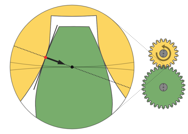
And finally, there aren’t too many times in life you’ll get a chance to get to visualize a number so large that an Evil Empire was named for it. The googol, or 10100, was a term coined by the nine-year-old nephew of mathematician Edward Kasner when he asked the child for a good name for a really big number. To put the immensity of that number into perspective, The Brick Experiment Channel on YouTube put together an improbably long gear train using Lego pieces we’ve never seen before with a reduction ratio of 10103.4:1. The gear train has a ton of different power transmission elements in it, from plain spur gears to worm drives and even planetary gears. We found the 2608.5:1 harmonic gear particularly fascinating. There’s enough going on to keep even a serious gearhead entertained, but perhaps not for the 5.2×1091 years it’ll take to revolve the final gear once. Something, something, heat-death of the universe. [Ed note: prior art, which we were oddly enough thinking of fondly just a few days ago. Synchronicity!]