Back when LCD character displays based on the HD44780 controller were the bee’s knees, a way to make them easier to work with came in the form of “backpack” PCBs, which provided an accessible serial interface and superior display handling at the same time. [Barbouri] has updated that idea with a backpack board that mounts to OLED displays using the US2066 display driver, and provides an I2C interface with powerful and convenient high-level functions that make the display simple to use.
On the software side, the backpack uses this I2cCharDisplay driver project which provides functions like cursor control, fading, display shifting, and of course writing characters or strings. While [Barbouri] designed the board specifically to accommodate Newhaven Slim Character OLED displays, it should in theory work with any US2066-based OLED character display. [Barbouri]’s design files for the Slim-OLED Display backpack board are available for download directly from the project page (link is near the bottom), or boards can be purchased directly from OSH Park.
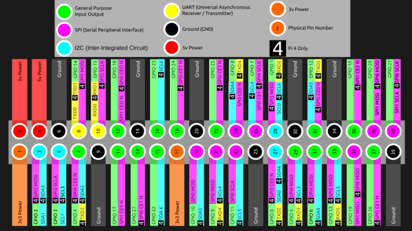
We’ve gotten used to the GPIO-available functions of Raspberry Pi computers remaining largely the same over the years, which is why it might have flown a little bit under the radar: the Raspberry Pi 4 has six SPI controllers, six I2C controllers, and six UARTs – all on its 40-pin header. You can’t make use of all of these at once, but with up to four different connections wired to a single pin you can carve out a pretty powerful combination of peripherals for your next robotics, automation or cat herding project.
The datasheet for these peripherals is pleasant to go through, with all the register maps nicely laid out – even if you don’t plan to work with the register mappings yourself, the maintainers of your preferred hardware enablement libraries will have an easier time! And, of course, these peripherals are present on the Compute Module 4, too. It might feel like such a deluge of interfaces is excessive, however, it lets you achieve some pretty cool stuff that wouldn’t be possible otherwise.
Having multiple I2C interfaces helps deal with various I2C-specific problems, such as address conflicts, throughput issues, and mixing devices that support different maximum speeds, which means you no longer need fancy mux chips to run five low-resolution Melexis thermal camera sensors at once. (Oh, and the I2C clock stretching bug has been fixed!) SPI interfaces are used for devices with high bandwidth, and with a few separate SPI ports, you could run multiple relatively high-resolution displays at once, No-Nixie Nixie clock style.
As for UARTs, the Raspberry Pi’s one-and-a-half UART interface has long been an issue in robotics and home automation applications. With a slew of devices like radio receivers/transmitters, LIDARs and resilient RS485 multi-drop interfaces available in UART form, it’s nice that you no longer have to sacrifice Bluetooth or a debug console to get some fancy sensors wired up to your robot’s brain. You can enable up to six UARTs. Continue reading “Did You Know That The Raspberry Pi 4 Has More SPI, I2C, UART Ports?”→
The Nintendo Game Boy and its many permutations represent one of the most well-known and successful gaming platforms ever produced. There was a decades-long stretch of time where the most popular kid in the lunch room was the one who brought in their Game Boy so the rest of the class could huddle around and check out the latest Pokemon title.
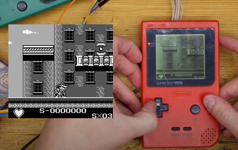
But those days are long gone, and now these once-coveted handhelds can be had for a song on the second-hand market. Which makes it the perfect time to check out this project [kgsws] released recently that allows you to interface the Game Boy LCD with the ESP32 or the Raspberry Pi. In the most basic of applications, it lets you push video from your Linux computer out to the Game Boy LCD over WiFi. But as the video below illustrates, that’s just the tip of the iceberg.
With the ESP32 wired between the handheld’s LCD and main PCB, the microcontroller can also act as a capture device using I2S camera mode. Compared to what ends up showing on the handheld’s LCD, the recorded gameplay [kgsws] shows off looks fantastic. Visuals are crisp and fluid, and naturally devoid of the Game Boy’s iconic (if slightly nauseating) greenish tint.
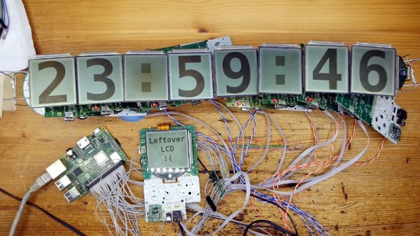
The project also includes the capability to control an array of Game Boy LCDs, which allows for some interesting possibilities. The image can be stretched to cover multiple displays, which [kgsws] demonstrates by playing a game on 3 x 3 grid of salvaged panels, but each LCD also can be controlled individually as is the case with the large digital clock seen above.
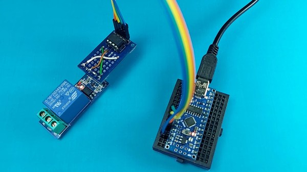
The Arduino is a powerful platform for interfacing with the real world, but it isn’t without limits. One of those hard limits, even for the Arduino MEGA, is a finite number of pins that the microcontroller can use to interface with the real world. If you’re looking to extend the platform’s reach in one of your own projects, though, there are a couple of options available. This project from [Bill] shows us one of those options by using the ATtiny85 to offload some of an Arduino’s tasks using I2C.
I2C has been around since the early 80s as a way for microcontrollers to communicate with each other using a minimum of hardware. All that is needed is to connect the I2C pins of the microcontrollers and provide each with power. This project uses an Arduino as the controller and an arbitrary number of smaller ATtiny85 microcontrollers as targets. Communicating with the smaller device allows the Arduino to focus on more processor-intensive tasks while giving the simpler tasks to the ATtiny. It also greatly simplifies wiring for projects that may be distributed across a distance. [Bill] also standardizes the build with a custom development board for the ATtiny that can also double as a shield for the Arduino, allowing him to easily expand and modify his projects without too much extra soldering.
Using I2C might not be the most novel of innovations, but making it easy to use is certainly a valuable tool to add to the toolbox when limited on GPIO or by other physical constraints. To that end, [Bill] also includes code for an example project that simplifies the setup of one of these devices on the software end as well. If you’re looking for some examples for what to do with I2C, take a look at this thermometer that communicates with I2C or this project which uses multiple sensors daisy-chained together.
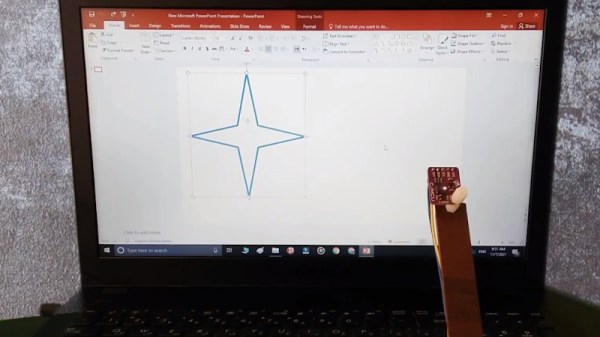
Controlling your computer with a wave of the hand seems like something from science fiction, and for good reason. From Minority Report to Iron Man, we’ve seen plenty of famous actors controlling their high-tech computer systems by wildly gesticulating in the air. Meanwhile, we’re all stuck using keyboards and mice like a bunch of chumps.
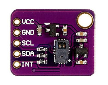
But it doesn’t have to be that way. As [Norbert Zare] demonstrates in his latest project, you can actually achieve some fairly impressive gesture control on your computer using a $10 USD PAJ7620U2 sensor. Well not just the sensor, of course. You need some way to convert the output from the I2C-enabled sensor into something your computer will understand, which is where the microcontroller comes in.
Looking through the provided source code, you can see just how easy it is to talk to the PAJ7620U2. With nothing more exotic than a switch case statement, [Norbert] is able to pick up on the gesture flags coming from the sensor. From there, it’s just a matter of using the Arduino Keyboard library to fire off the appropriate keycodes. If you’re looking to recreate this we’d go with a microcontroller that supports native USB, but technically this could be done on pretty much any Arduino. In fact, in this case he’s actually using the ATtiny85-based Digispark.
This actually isn’t the first time we’ve seen somebody use a similar sensor to pull off low-cost gesture control, but so far, none of these projects have really taken off. It seems like it works well enough in the video after the break, but looks can be deceiving. Have any Hackaday readers actually tried to use one of these modules for their day-to-day futuristic computing?
Imagine you’re sending a piece of hardware to space on a satellite. Unless you’re buddy-buddy with NASA, it’s pretty unlikely you’ll ever be able to head up there and fix something if it goes wrong once it’s launched. Robust design is key, so that even in the event of a failure in one component, the rest of the hardware can keep working.
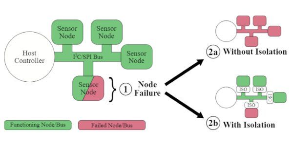
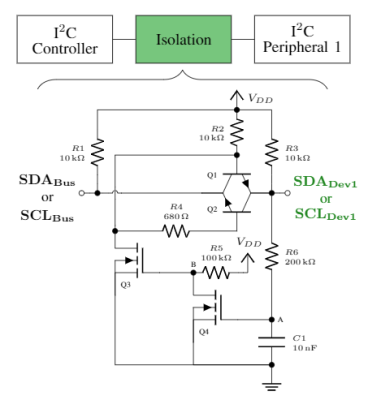
The example I2C isolation circuit from [Max’s] paper. The SPI implementation is even simpler.[Max Holliday] found himself in this exact situation, running 69 I2C and SPI devices in a single satellite. Thus, he came up with circuits to auto-isolate devices from these buses in the event of an issue. That work is the subject of a research paper now available on the TechRxiv Preprint Server.
The problem is that these simple buses aren’t always the most robust, being vulnerable to single-point failures where one bad part takes down other parts of the bus. [Max] notes that vast numbers of sensors and devices rely on these standards, and it can be difficult or prohibitively expensive to design without them, so a solution was needed.
To fix this, [Max] developed a simple external circuit that could be placed on each node of a I2C or SPI communication bus. In the event of malfunction, that node can be cut off from the bus by this circuit, allowing the rest of the system to go on functioning.
With little more than a few transistors, MOSFETs and passives, you too could protect your buses from malfunctions using these techniques. [Max] did just that on the NASA V-R3x mission which flew successfully in January 2021 if you needed any further confirmation of the value of this technique.
It’s something that won’t bother the home hobbyist building a garage door opener, but it could be of great value to those designing systems that must fail gracefully if they fail at all. Be sure to share your best tips and tricks for robust SPI and I2C buses in the comments below!
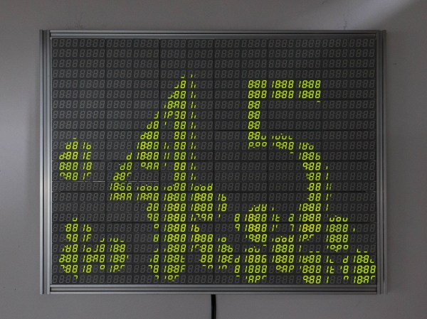
If you look around your desk right now, odds are you’ll see a 7-segment display or two showing you some vital information like the time or today’s weather. But think of how much information you could see with over 1,100 digits, like with [Chris Combs’] 7200-segment display.
For [Chris], this project started the same way that many of our projects start; finding components that were too good of a deal to pass up on. For just “a song or two plus shipping”, he was the proud owner of two boxes of 18:88 7-segment displays, 500 modules in total. Rather than sitting and using up precious shelf space, [Chris] decided to turn them into something fancy he could hang on the wall.
The IS31FL3733 can produce 8 levels of dimming 8-bit PWM, allowing [Chris] to display in grayscaleThe first challenge was trying to somehow get a signal to all of the individual segments. Solutions exist for running a handful of displays in one device, but there are certainly no off-the-shelf solutions for this many. Even the possible 16 addresses of the IS31FL3733 driver IC [Chris] chose for this project were not enough, so he had to get creative. Fearing potential capacitance issues with simply using an i2C multiplexer, he instead opted to run 3 different i2C busses off of a Raspberry Pi 4, to interface with all 48 controllers.
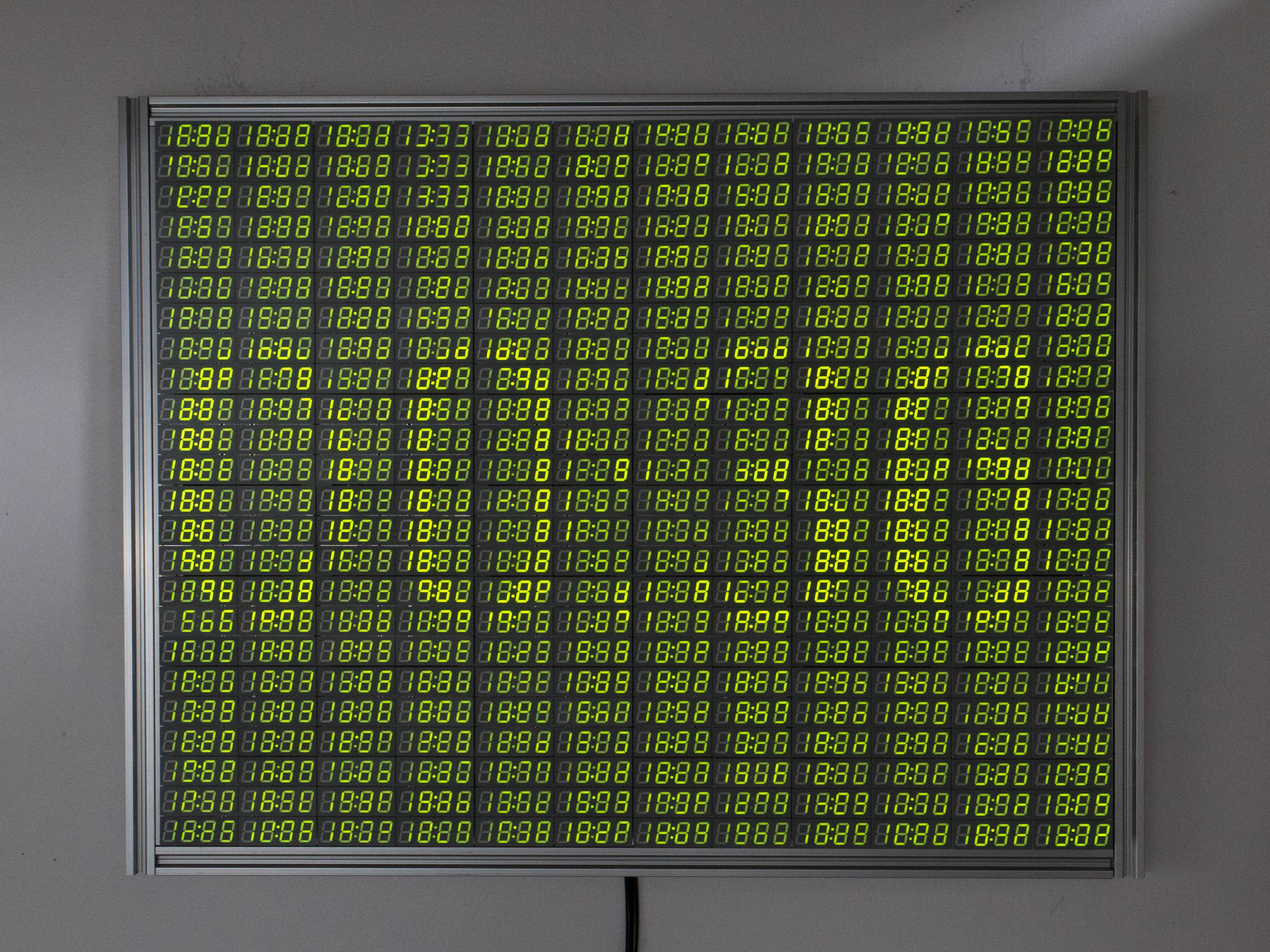
The second challenge was how to actually wire everything up. The finished display comes out to 26 inches across by 20.5 inches tall, much too large for a single PCB. Instead, [Chris] opted to design a series of self-contained panels, each with 6 of the display modules and an IS31FL3733 to drive them. While the multiplexing arrangement did leave space for more segments on each panel, he opted to go for this arrangement as it resulted in a nice, clean, 4:3 aspect ratio for the final display.
The end result was a unique and beautiful piece, which Chris titled “One-to-Many”. He uses it to display imagery and art related to the inevitability of automation, machines replacing humans, and other “nice heartwarming stuff like that”, as he puts it. There’a video after the break, but if you are interested in seeing the display for yourself, it will be on display at the VisArt’s Concourse Gallery in Rockville, MD from September 3 to October 17, 2021. More info on [Chris’s] website.
 On the software side, the backpack uses this I2cCharDisplay driver project which provides functions like cursor control, fading, display shifting, and of course writing characters or strings. While [Barbouri] designed the board specifically to accommodate Newhaven Slim Character OLED displays, it should in theory work with any US2066-based OLED character display. [Barbouri]’s design files for the Slim-OLED Display backpack board are available for download directly from the project page (link is near the bottom), or boards can be purchased directly from OSH Park.