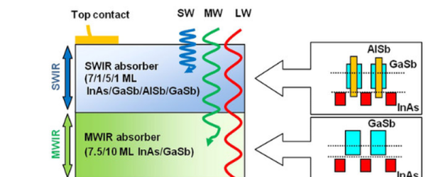
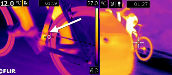
Just Don’t Call It An Old Remote

[Hari Wiguna’s] father is ninety years young. He started having trouble pushing the buttons on his TV remote, so [Hari] decided to build a custom remote that just has the buttons his dad needs. Oh, and the buttons are big.

There are a few interesting things about this project. [Hari] wanted to maximize battery life, so he went through a good bit of effort to keep the processor asleep and minimize power consumption. The remote is programmable, but [Hari] didn’t have access to his dad’s remotes. His answer was elegant. He used his Android phone to mimic the required remotes and provided a way for the remote to learn from another remote (in this case, the phone).
Continue reading “Just Don’t Call It An Old Remote”

Becoming A Zombie With The Hackable Electronic Badge

Last week, Parallax released an open hackable electronic badge that will eventually be used at dozens of conferences. It’s a great idea that allows badge hacks developed during one conference to be used at a later conference.

[Mark] was at the Hackable Electronics Badge premier at the 2015 Open Hardware Summit last weekend, and he just finished up the first interactive hack for this badge. It’s the zombie apocalypse in badge form, pitting humans and zombies against each other at your next con.

The zombie survival game works with the IR transmitter and receiver on the badge normally used to exchange contact information. Upon receiving the badge, the user chooses to be either a zombie or survivor. Pressing the resistive buttons attacks, heals, or infects others over IR. The game is your standard zombie apocalypse affair: zombies infect survivors, survivors attack zombies and heal the infected, and the infected turn into zombies.

Yes, a zombie apocalypse is a simple game for a wearable with IR communications, but for the Hackable Electronics Badge, it’s a great development. There will eventually be tens of thousands of these badges floating around at cons, and having this game available on day-one of a conference will make for a lot of fun.

Hackaday Prize Entry: Open-source Pulse Oximetry

Chances are pretty good you’ve had a glowing probe clipped to your fingertip or earlobe in some clinic or doctor’s office. If you have, then you’re familiar with pulse oximetry, a cheap and non-invasive test that’s intended to measure how much oxygen your blood is carrying, with the bonus of an accurate count of your pulse rate. You can run down to the local drug store or big box and get a fingertip pulse oximeter for about $25USD, but if you want to learn more about photoplethysmography (PPG), [Rajendra Bhatt]’s open-source pulse oximeter might be a better choice.

PPG is based on the fact that oxygenated and deoxygenated hemoglobin have different optical characteristics. A simple probe with an LED floods your fingertip with IR light, and a photodiode reads the amount of light reflected by the hemoglobin. [Rajendra]’s Easy Pulse Plugin receives and amplifies the signal from the probe and sends it to a header, suitable for Arduino consumption. What you do with the signal from there is up to you – light an LED in time with your heartbeat, plot oxygen saturation as a function of time, or drive a display to show the current pulse and saturation.

We’ve seen some pretty slick DIY pulse oximeters before, and some with a decidedly home-brew feel, but this seems like a good balance between sophisticated design and open source hackability. And don’t forget that IR LEDs can be used for other non-invasive diagnostics too.

The 2015 Hackaday Prize is sponsored by:

Remote Tester

A Simple Circuit For Testing Infrared Remote Controls

Every now and then a remote control acts up. Maybe you are trying to change the channel on your television and it’s just not working. A quick way to determine if the remote control is still working is by using a cell phone camera to try to see if the IR LED is still lighting up. That can work sometimes but not always. [Rui] had this problem and he decided to build his own circuit to make it easier to tell if a remote control was having problems.

The circuit uses a Vishay V34836 infrared receiver to pick up the invisible signals that are sent from a remote control. A Microchip 12F683 processes the data and has two main output modes. If the remote control is receiving data continuously, then a green LED lights up to indicate that the remote is functioning properly. If some data is received but not in a continuous stream, then a yellow LED lights up instead. This indicates that the batteries on the remote need to be replaced.

The circuit also includes a red LED as a power indicator as well as RS232 output of the actual received data. The PCB was cut using a milling machine. It’s glued to the top of a dual AAA battery holder, which provides plenty of current to run the circuit.

Wildlife Camera

Remote Controlled Wildlife Camera With Raspberry Pi

If you are interested in local wildlife, you may want to consider this wildlife camera project (Google cache). [Arnis] has been using his to film foxes and mice. The core components of this build are a Raspberry Pi and an infrared camera module specifically made for the Pi. The system runs on a 20,000 mAh battery, which [Arnis] claims results in around 18 hours of battery life.

[Arnis] appears to be using a passive infrared (PIR) sensor to detect motion. These sensors work by detecting sudden changes in the amount of ambient infrared radiation. Mammals are good sources of infrared radiation, so the sensor would work well to detect animals in the vicinity. The Pi is also hooked up to a secondary circuit consisting of a relay, a battery, and an infrared light. When it’s dark outside, [Arnis] can enable “night mode” which will turn on the infrared light. This provides some level of night vision for recording the furry critters in low light conditions.

[Arnis] is also using a Bluetooth dongle with the Pi in order to communicate with an Android phone. Using a custom Android app, he is able to connect back to the Pi and start the camera recording script. He can also use the app to sync the time on the Pi or download an updated image from the camera to ensure it is pointed in the right direction. Be sure to check out the demo video below.

If you like these wildlife cameras, you might want to check out some older projects that serve a similar purpose. Continue reading “Remote Controlled Wildlife Camera With Raspberry Pi”

Control Anything With An Apple Remote

If you’re like us, you probably have more than one Apple Remote kicking around in a parts drawer, and if you’re even more like us, you’re probably really annoyed at Apple’s tendency to use proprietary hardware and software at every turn (lightning connector, anyone?). But there’s hope for the Apple Remote now: [Sourcery] has completed a project that allows an Apple Remote to control anything you wish.

The idea is fairly straightforward: A device interprets the IR signals from an Apple Remote, and then outputs another IR signal that can do something useful on a non-Apple product. [Sourcery] uses an Arduino to do the IR translation, along with a set of IR emitters and detectors, and now the Apple Remote can control anything, from stereos to TVs to anything you can imagine. It also doesn’t remove the Apple Remote’s capability to control Apple products, in case you need yours to do that as well.

[Sourcery] notes that sometimes working with RAW IR signals can be a little difficult, but the information on their project and in their 25-minute video discusses how to deal with that, so make sure to check that out after the break. Don’t have an Apple Remote? You can do a similar thing with a PS3 controller.

Continue reading “Control Anything With An Apple Remote”

Camera Controller

A Remote For CHDK Cameras Made Possible With Arduino

[AlxDroidDev] built himself a nice remote control box for CHDK-enabled cameras. If you haven’t heard of CHDK, it’s a pretty cool software modification for some Canon cameras. CHDK adds many new features to inexpensive cameras. In this case, [AlxDroidDev] is using a feature that allows the camera shutter to be activated via USB. CHDK can be run from the SD card, so no permanent modifications need to be made to the camera.

[AlxDroidDev’s] device runs off of an ATMega328p with Arduino. It operates from a 9V battery. The circuit contains an infrared receiver and also a Bluetooth module. This allows [AlxDroidDev] to control his camera using either method. The device interfaces to the camera using a standard USB connector and cable. It contains three LEDs, red, green, and blue. Each one indicates the status of a different function.

The Arduino uses Ken Shirrif’s IR Remote library to handle the infrared remote control functions. SoftwareSerial is used to connect to the Bluetooth module. The Arduino code has built-in functionality for both Canon and Nikon infrared remote controls. To control the camera via Bluetooth, [AlxDroidDev] built a custom Android application. The app can not only control the camera’s shutter, but it can also control the level of zoom.