Chaining Together A 16×2 Bubble LED Display

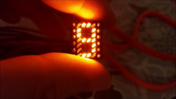
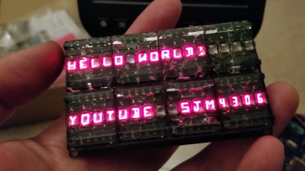
We’ve recently noticed an uptick of interest in so-called “bubble displays”: vintage alphanumeric LEDs which are probably best remembered as being used in watches and calculators before the LCD took over. Today they’re available as surplus or even salvage for literally pennies, but unfortunately they only provide four or five characters to work with. Or rather they did, until [sjm4306] built a board that chains them into a 16×2 array.

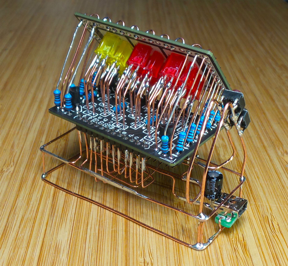
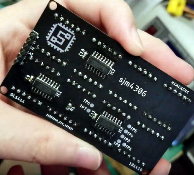
For the princely sum of 71 cents each, [sjm4306] picked up ten HPDL-1414 displays, each capable of showing four characters. He then designed a PCB that would accept eight of the displays at once, and even thought ahead to use headers so they could be pulled out and swapped as needed. Of course mounting them is only half the battle, you still need to drive the things.

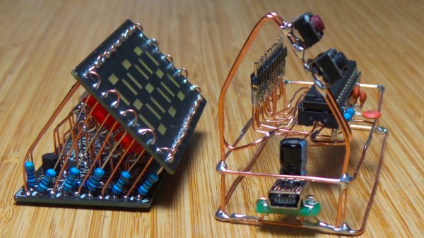
Each display has its own dedicated driver chip on board, but trying to address each one individually would take far too many pins. So [sjm4306] opted to use a trio of 74HC595 shift registers, allowing him to toggle the three dozen pins necessary over SPI from a microcontroller. He’s even written up a little library and some example code that you can grab on the project’s Hackaday.io page.

Unfortunately, after all his hard work, tragedy struck. As these displays were a couple decades old given their date code, [sjm4306] thought he would clean them up with a bit of alcohol before their big video debut. But whatever plastic the clear panels are made of didn’t take kindly to the IPA, and they all shattered. They still work, but it’s definitely a quirk to keep in mind if you pick up some of these vintage displays to play with yourself.

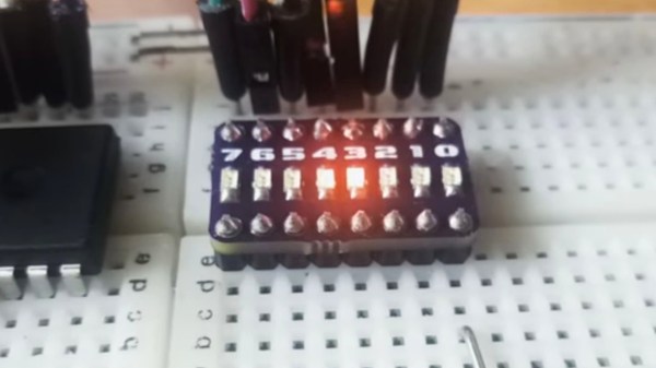
In the past we’ve seen a much smaller PCB that allowed similar displays to more easily be interfaced with modern microcontrollers; perfect if you just want to bang out a few retro LED characters with a minimum of fuss.

Continue reading “Chaining Together A 16×2 Bubble LED Display”

LED Driver Board Could Be Your Ticket To FPGA Development

Microcontrollers are a great way to learn about developing for embedded systems. However, once you outgrow their capabilities, FPGAs bring muscle that’s hard for even the fastest-clocked micros to match. If you’re doing anything with high-speed signals, loads of RAM, or something that requires lots of parallel calculation, you can’t go past FPGAs. Dev boards can be expensive, but there are alternatives. There’s a nifty project on Github trying to repurpose commodity hardware into a useful FPGA development platform.

Chubby75 is a project to reverse engineer the RV901T LED “Receiver Card”. This device is used to receive signals over Ethernet, and clock data out to large LED displays. This sort of work is highly processor intensive for microcontrollers, but a cinch for FPGAs to manage. The board packs a user-reprogrammable Spartan 6 FPGA, along with twin Gigabit Ethernet ports and 64MB of SDRAM. Thanks to the fact that its firmware is not locked down, it has the potential to be repurposed into all manner of other projects. The boards are available for under $30 USD, making them a prime target for thrifty hackers.

Thus far, the team have begun poring through the hardware documentation and are looking to develop a toolchain to allow the boards to be easily reprogrammed. With the right tools, these boards could be the next thing in cheap FPGAs, taking over when the Pano Logic thin clients become thin on the ground.

[Thanks to KAN for the tip!]

Visualizing LEDs For More Efficient Pin Packing

The archetypal “blink an LED” is a great starter project on any platform, but once the bug takes hold that quickly turns into an exploration of exactly how many LEDs a given microcontroller can drive. And that often leads to Charlieplexing. A quick search yields many copies of The Table describing how many LEDs can be driven by a given number of pins but that’s just the most rudimentary way to describe it. Way back in 2013 [M Rule] developed a clever trick to describe the number of LED matrices which can be driven by a Charlieplexed array of a given size that makes this process much more intuitive. The post may be old, but we promise the method is still fresh.

[M Rule] was specifically looking to drive those big, cheap single color LED matrices which are often used to make scrolling signs and the like. These parts are typically a matrix of LEDs with a row of common cathodes and one of common anodes. Internally they are completely dumb and can be driven by row/column scanning, or any other way a typical matrix can be controlled. The question is, given known matrix sizes, how many can be driven with a a number of Charlieplexed LED drive pins?

The first step is to visualize the 1D array of available pins as a 2D matrix, as seen to the right. Note each numbered pin is the same on the X and Y, thus the black exclusion zone of illegal drive pin combinations slicing across the graph (you can’t drive an LED connected to one pin twice). The trick, if one were to say it resides in a single place, would be titling the axis anode and cathode, representing two “orientations” the drive pins can be put in. With this diagram [M Rule] observed you can simply drop a matrix into the array. If it fits outside the exclusion zone, it can be driven by those pins!

To the left is what this looks like with two 8×8 matrices, one connected between pins 1-8 and 9-16, the other connected between 9-16 and 1-8. This isn’t terribly interesting, but the technique works just as well with single LEDs and any size matrix, including 7-segment displays. Plus as long as an element doesn’t overlap itself it can wrap around the edges leading to some wild visuals, like 14 RGB LEDs on seven pins to the right.

The most extreme examples are pretty exotic. Check out [M Rule]’s post for the crown jewel; 18 pins to drive six 5×7 modules, six 7-segment displays, 12 single LEDs, and 18 buttons!

If this color coded diagram seems familiar, you may be remembering [openmusiclabs]’ excellent diagram describing ways to scan many of buttons. Or our coverage of another trick of matrix topology by [M Rule] from a few weeks ago.

Make Your Own Old School LED Displays

We live in an era in which all manner of displays are cheap and readily available. A few dollars spent online can net you a two-line alphanumeric LCD, a graphical OLED screen, or all manner of other options. Years ago however, people made do with little monolithic LED devices. [sjm4306] wanted to recreate something similar, and got down to work (Youtube link, embedded below).

The resulting device uses 0603 sized SMD LEDs, soldered onto a tiny PCB. 20 LEDs are used per digit, which can display numbers 0-9 and letters A-F. The LEDs are laid out in a pattern similar to Hewlett-Packard designs from years past. This layout gives the numerals a more pleasant appearance compared to a more-classic 7-segment design. Several tricks are used to make the devices as compact as possible, such as putting vias in the LED pads. This is normally a poor design technique, but it helps save valuable space.

[sjm4306] has developed a breadboard model, and a more advanced version that has a pad on the rear to mount a PIC16F88 microcontroller directly. We look forward to seeing these modules developed further, and can imagine they’d prove useful in a variety of projects.

For reference, check out these Soviet-era 7-segment displays. Video after the break.

Continue reading “Make Your Own Old School LED Displays”

Lateral Thinking For An Easier Charlieplex

In the practical world we live in, PCBs are often rectangles (or rectangles with rectangles, it’s just rectangles all the way down). When a designer goes to schematic capture things are put down on nice neat grid intersections; and if there isn’t a particular demand during layout the components probably go on a grid too. Routing even the nastiest fractal web of traces is mostly a matter of layers and patience. But if the layout isn’t being done in a CAD tool and needs to be hand assembled free-form this isn’t always as simple. [M Rule] had this very problem and discovered a clever solution, turning things diagonal.

They changed the fitness criteria to the optimization problem that is controlling a lot of LEDs. Instead of minimum pins to drive the goal became “easiest assembly”, which meant avoiding wires snaking back and forth across the layout, a big source of frustration in a big Charlieplexed design. The observation was that if they turned the a rectilinear LED matrix by 45° and wrapped each connection around at the edges it formed what was essentially a large multiplexed matrix. The topology is pretty mind bending, so take a minute to study the illustration and build your mental model.

It looks a little strange, but this display works the same way a normal multiplexed display does but with the added benefit that each trace flows from one side to the other without turning back on itself at any point. To light any LED set the right row/column pair as source/sink and it turns on!

What if you actually need a rectangular display? Well that’s no problem, the matrix can be bent and smooshed as desired to change its shape. At the most extreme the possible display topologies get pretty wild! We’re sure to try thinking laterally next time we need to design an unusual display, maybe there is a more efficient matrix to be found.

A Perfectly Orderly Way To Manage Your Time

[Paul Gallagher] has spent years separating his tasks into carefully measured out blocks, a method of time management known as the Pomodoro Technique. If that’s not enough proof that he’s considerably more organized and structured than the average hacker, you only need to take a look at this gorgeous Pomodoro Timer he’s entered into the Circuit Sculpture Contest. Just don’t be surprised if you suddenly feel like your own time management skills aren’t cutting it.

While [Paul] has traditionally just kept mental note of the hour-long blocks of time he breaks his work into, he thought it was about time he put together a dedicated timer to make sure he’s running on schedule. Of course he could have used a commercially available timer or an application on his phone, but he wanted to make something that was simple and didn’t cause any distractions. A timer that was easy to start, reliable, and didn’t do anything extraneous. We’re not sure if looking like the product of a more advanced civilization was part of his official list of goals, but he managed to achieve it in any event.

The timer is broken up into two principle parts: the lower section which has the controls, USB port, a handful of passive components, and an ATmega328 microcontroller, and the top section which makes up the three digit LED display. The two sections are connected by a header on the rear side which makes it easy for [Paul] to take the timer apart if he needs to get back into it for any reason. Notably absent in the design is a RTC; the relatively short duration of the timer (up to a maximum of 95 minutes) means the ATmega328 can be trusted to keep track of the elapsed time itself with an acceptable amount of drift.

The display side of the timer is really a sight to behold, with the legs of each LED soldered to a pair of carefully bent copper wires so they match the angle of the front panel. The associated resistors have been artfully snipped so that their bodies sit flat on the PCB while their leads reach out to the perfect length. It looks like a maintenance nightmare in there, but we love it anyway.

As we near the half-way mark of the Circuit Sculpture Contest, there’s still plenty of time to submit your own piece of functional art. If you’ve got a project that eschews the printed circuit board for a chance to bare it all, write it up on Hackaday.io and be sure to send it in before the January 8th, 2019 deadline.

Continue reading “A Perfectly Orderly Way To Manage Your Time”

One-byte binary LED display

See Binary On Your Breadboard

When you’re debugging a board which has an ESP32, Raspberry Pi, or Arduino, it’s easy to slap on a small LCD display or connect via WiFi to see what’s wrong. At least, that’s what the kids are doing. But what if you’re old-school or you don’t have one of those pimped-out, steroid-filled boards? A resistor and an LED will often suffice. Powering the LED means one thing and not powering it means another. And with seven more LEDs you can even display 0-255 in binary.

[Miguel] is clearly in the latter camp. To make debugging-with-LEDs easy, he’s come up with an 8-LED board complete with resistors. He’s even included the Gerber files needed for you to make your own. One row of pins are all connected together and the other row are not. So whether you’re using common cathode or common anode depends on how you orient the LEDs when you solder them in place. You might perhaps have one board of each type at the ready.

But who are we kidding? This is just plain fun to have on a breadboard. Show your prototype doohickey to a friend and you know they’ll be drawn to the little binary counter in the corner pulsing 42 or counting down until it starts flashing 255.

At risk of getting too feature-rich, you could then add two keys for a binary keyboard or add more LEDs to display 32-bit binary Unix Epoch time and see how long until your friends figure that one out.

Continue reading “See Binary On Your Breadboard”