Physical Tone Matrix

[Andrew Jenner] pulled off something amazing with this Physical Tone Matrix. He wanted to build a physical version of a flash applet he had seen. Two layers make up the main user interface. The top layer is a sheet of acrylic that acts as a touch interface and below there’s an LED matrix. [Andrew’s] touch interface uses wires running throughout the acrylic as contacts which are polled via transistor pairs. As you can see in the video after the break it works well and we like the fact that there’s a tactile component (due to the bumpy wires) you don’t get when working with a touchscreen.

The 16×16 grid of LEDs on the bottom layer correspond to each ‘button’ on the touch matrix hand have some extra functions such as playing Conway’s Game of Life. This fantastic build still has a couple of kinks to work out, most notably the interference in the audio circuit, but we’re quite impressed at what he’s achieved quickly. Plus, this is more economical than a monome and larger than some of the monome clones we’ve seen.

Continue reading “Physical Tone Matrix”

Giant LED Matrix

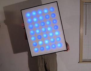
We all love blinky lights. What we love even more than blinky lights is a very detailed tutorial with great photos. [Richard Kline] has written this fantastic tutorial on how to build a large 5×7 LED matrix and control it with a PIC processor.  The bulk of the body is a foam insulation board, covered with a diffuser. Source code and schematics are available for download from the site. If you’ve ever thought about getting into PIC processors, this would be a great beginner project.

[via MakeZine]

Printed Circuit Board Minus The Printed Traces

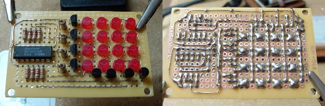
Reader [Osgeld] is a board-layout ninja. He populated this 4×4 LED matrix board without having a layout plan to start with. Watch it develop in slideshow format to see the art work he performs. The display is driven by a shift-register and he’s included all the proper parts like resistors and transistors, yet he makes everything fit. Why is this amazing? He’s using uninsulated wire and not a single one of them crosses another wire. He’s physically designing a printed circuit board, routing the traces as he solders away. He’s built this to use with an Arduino shift register tutorial and our only question is where is the header to hook this board to a microcontroller?

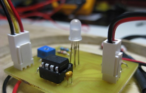
Color Clock Makes Telling Time Impossible

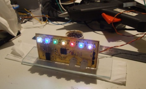
[Bogdan] set out to build the all-too-familiar binary clock. But, he didn’t want to be ordinary, and set the goal of making the clock as hard to read as possible. What he ended up with is a clock that is almost impossible to read correctly.
He’s using colors to tell the time. We immediately thought this might make use of resistor codes as the display but it doesn’t. Red shows the hours, green for minutes, and blue for seconds. Now stack all of them on top of each other in binary and you’ve got the time. That means you’ve got to know all of your color combinations, plus read the binary value correctly, to decipher the time. Add to that the display changing every second and we’re in trouble.
Aside from the user difficulty level, this is a really clean build. It uses an ATmega8535 in conjunction with our favorite DS3232 RTC chip. The etched board is nice and clean, making for an aesthetically pleasing clock.

Six Digit LED Clock

Got a bag of LEDs handy? Why not build a display with them? We’ve seen a lot of clocks that make use of LED modules but soldering your own is a fun pastime. [Vadim Suhovatih] did just that using 130 LEDs to build this clock. Each segment of the 7-segment digits consists of three LEDs in parallel which are switched by some 2N4401 transistors. An ATmega328 in the form of an Arduino controls the device with the aid of a DS1307 real-time clock for timekeeping and a 4017 decade counter to assist with scanning the display. Check out the demo after the break.

Continue reading “Six Digit LED Clock”

Switchmode LED Flashlight Upgrade

When [Neelandan]’s cheap flashlight’s internal rechargeable battery died, he scrounged for a replacement. Ultimately, the brightness of the light suffered with his new battery, taken from an old cell phone since he had dropped the voltage a bit. Upon inspection he saw that he would have to swap the individual resistors for each lamp to get the desired brightness again. This wasn’t really acceptable as he would have to repeat the process if he used another re-purposed battery with different specs. Instead, he added a new circuit to supply constant brightness until the voltage drops below 2.7 volts. We love to see hardware resurrected, even if it is just a cheap LED flashlight.