Need High-Power Li-Ion Charging? How About 100 W

Ever want a seriously powerful PCB for charging a Li-Ion pack? Whatever you want it for, [Redherring32] has got it — it’s a board bearing the TPS25750D and BQ25713 chips, that lets you push up to 100 W into your 1S Li-Ion pack through the magic of USB Power Delivery (USB-PD).

Why do you need so much power? Well, when you put together a large amount of Li-Ion cells, this is how you charge it all at once – an average laptop might charge the internal battery at 30 W, and it’s not uncommon for laptop batteries to be dwarfed by hackers’-built packs.

A 4-layer creation peppered with vias, this board’s a hefty one — it’s not often that you see a Li-Ion charger designed to push as much current as possible into a cell, and the chips are smart enough for that. As far as the onboard chips’ capabilities go, the board could handle pack configurations from 1S to 4S, and even act as a USB-PD source — check the IC configuration before you expect to use it for any specific purpose.

Want a simpler charger, even if it’s less powerful? Remember, you can use PPS-capable PD chargers for topping up Li-Ion packs, with barely any extra hardware required.

Upgrading A Cheap LX-2BUPS UPS Board To Fix Fatal Flaws

Cheap uninterruptable power supply (UPS) boards that take Li-ion cells of some description seem to have cropped up everywhere the past years. Finding use in applications such as keeping single-board computers ticking along in the case of a power failure, they would seem to be a panacea. Unfortunately most of these boards come with a series of fatal flaws, such as those that [MisterHW] found in an LX-2BUPS board obtained from AliExpress. Worst of all was the deep discharge of the Li-ion cells to below 2 V, which took some ingenuity and hard work to fix this and other problems.

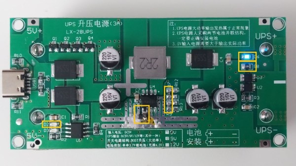
The patched up XR2981 boost IC with MCP809 reset IC installed. (Credit: [MisterHW])
This particular board is rated for 5V at 3A, featuring the all too common TP4056 as charging IC and the XYSemi XR2981 boost converter. Since there is no off-switch or other protections on the board, the XR2981 will happily keep operating until around 2.6V, at a rather astoundingly high idle power consumption. Because of this the fixes mostly concentrated on optimizing the XR2981, by using better resistor values (R7, R8, R9), as well as adding a 3.15V MCP809 reset IC, to reduce idle power usage of the boost converter and disable it below a safe cell voltage.

The final coup de grâce was the eviction of the red LED (D6) and replacing it with the blue LED from D2, to stop the former from draining the cell as well. With these changes in place, no-load power usage dropped from nearly 900 µA to just over 200 µA, while preventing deep discharge. Although this board now has a second life, it does raise the question of what the point of these cheap UPS boards is if you have to spend money and time on reworking them before they’re somewhat acceptable. What is your go-to solution for these boards?

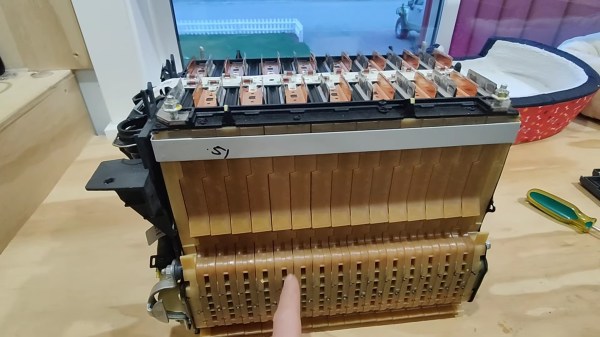
A finger points at a stack of yellow plastic plates sandwiched together like on a bookshelf. A grey metal rectangle holds the top together and black plastic sticks off to the left. The top of the pack has copper and nickel (or some other silver-colored metal) tabs pointing up out of the assembly.

Tearing Into A Sparky Sandwich

We’re still in the early days of modern EV infrastructure, so minor issues can lead to a full high voltage pack replacement given the lack of high voltage-trained mechanics. [Ed’s Garage] was able to source a Spark EV battery pack that had succumbed to a single bad cell and takes us along for the disassembly of the faulty module.

The Spark EV was the predecessor to the more well-known Chevy Bolt, so its nearly ten year old systems might not reflect the state-of-the-art in EV batteries, but they are certainly more modern than the battery in your great-grandmother’s Baker Electric. The Li-ion polymer pouch cells are sandwiched together with cooling and shock absorbing panels to keep the cells healthy and happy, at least in theory.

In a previous video, [Ed’s Garage] takes apart the full pack and shows how the last 2P16S module has assumed a darker color on its yellow plastic, seeming to indicate that it wasn’t receiving sufficient cooling during its life in the car. It would seem that the cooling plates inside the module weren’t quite up to the task. These cells are destined for other projects, but it doesn’t seem like this particular type of battery module would be too difficult to reassemble and put back in a car as long as you could get the right torque settings for the compression bolts.

If you’re looking for other EV teardowns, might we suggest this Tesla Model S pack or one from a passively-cooled Nissan Leaf?

Continue reading “Tearing Into A Sparky Sandwich”

A 48 Volt Battery Pack With Carefully Balanced Cells

Many readers will have at some time or another built their own lithium-ion battery packs, whether they are using tiny cells or the huge ones found in automotive packs. A popular choice it to salvage ubiquitous 18650 cylindrical cells, as [limpkin] has with this 48 volt pack. It’s based around an off-the-shelf kit aimed at the e-bike market, but it’s much more than a simple assembly job.

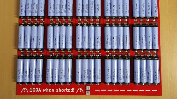
Faced with a hundred salvaged cells of unknown provenance, the first thing to do was ensure that they were all balanced and showed the same voltage. Some might do this the inefficient way by hooking each one up to a charger and a programmable load, but in this case a much more radical route was taken. A huge PCB was designed with sockets for all hundred cells, connected in parallel through individual series resistors. This allowed them to balance to a common voltage before being discharged to a safe voltage for assembly. Their individual ESRs were the measured, and the best performing examples were then spot-welded into the final 13s-6p final pack.

We all use lithium-ion batteries, but how many of us know how they work?

This Open Hardware Li-Ion Charger Skips The TP4056

There’s a good chance that if you build something which includes the ability to top up a lithium-ion battery, it’s going to involve the incredibly common TP4056 charger IC. Now, there’s certainly nothing wrong with that. It’s a decent enough chip, and there are countless pre-made modules out there that make it extremely easy to implement. But if the chip shortage has taught us anything, it’s that alternatives are always good.

So we’d suggest bookmarking this opensource hardware Li-Ion battery charger design from [Shahar Sery]. The circuit uses the BQ24060 from Texas Instruments, which other than the support for LiFePO4 batteries, doesn’t seem to offer anything too new or exciting compared to the standard TP4056. But that’s not the point — this design is simply offered as a potential alternative to the TP4056, not necessarily an upgrade.

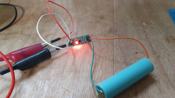
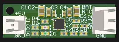
[Shahar] has implemented the design as a 33 mm X 10 mm two-layer PCB, with everything but the input and output connectors mounted to the topside. That would make this board ideal for attaching to your latest project with a dab of hot glue or double-sided tape, as there are no components on the bottom to get pulled off when you inevitably have to do some rework.

The board takes 5 VDC as the input, and charges a single 3.7 V cell (such as an 18650) at up to 1 Amp. Or at least, it can if you add a heatsink or fan — otherwise, the notes seem to indicate that ~0.7 A is about as high as you can go before tripping the thermal protection mode.

Like the boilerplate TP4056 we covered recently, this might seem like little more than a physical manifestation of the typical application circuit from the chip’s datasheet. But we still think there’s value in showing how the information from the datasheet translates into the real-world, especially when it’s released under an open license like this.

Researchers Find “Inert” Components In Batteries Lead To Cell Self-Discharge

When it comes to portable power, lithium-ion batteries are where it’s at. Unsurprisingly, there’s a lot of work being done to better understand how to maximize battery life and usable capacity.

Red electrolytic solution, which should normally be clear.

While engaged in such work, [Dr. Michael Metzger] and his colleagues at Dalhousie University opened up a number of lithium-ion cells that had been subjected to a variety of temperatures and found something surprising: the electrolytic solution within was a bright red when it was expected to be clear.

It turns out that PET — commonly used as an inert polymer in cell assembly — releases a molecule that leads to self-discharge of the cells when it breaks down, and this molecule was responsible for the color change. The molecule is called a redox shuttle, because it travels back and forth between the cathode and the anode. This is how an electrochemical cell works, but the problem is this happens all the time, even when the battery isn’t connected to anything, causing self-discharge.

Continue reading “Researchers Find “Inert” Components In Batteries Lead To Cell Self-Discharge”

Ryobi Battery Hack Keeps CPAP Running Quietly

When it comes to cordless power tools, color is an important brand selection criterion. There’s Milwaukee red, for the rich people, the black and yellow of DeWalt, and Makita has a sort of teal thing going on. But when you see that painful shade of fluorescent green, you know you’ve got one of the wide range of bargain tools and accessories that only Ryobi can offer.

Like many of us, Redditor [Grunthos503] had a few junked Ryobi tools lying about, and managed to cobble together this battery-powered inverter for light-duty applications. The build started with a broken Ryobi charger, whose main feature was a fairly large case once relieved of its defunct guts, plus an existing socket for 18-volt battery packs. Added to that was a small Ryobi inverter, which normally plugs into the Ryobi battery pack and converts the 18 VDC to 120 VAC. Sadly, though, the inverter fan is loud, and the battery socket is sketchy. But with a little case modding and a liberal amount of hot glue, the inverter found a new home inside the charger case, with a new, quieter fan and even an XT60 connector for non-brand batteries.

It’s a simple hack, but one that [Grunthos503] may really need someday, as it’s intended to run a CPAP machine in case of a power outage — hence the need for a fan that’s quiet enough to sleep with. And it’s a pretty good hack — we honestly had to look twice to see what was done here. Maybe it was just the green plastic dazzling us. Although maybe we’re too hard on Ryobi — after all, they are pretty hackable.

Thanks to [Risu no Kairu] for the tip on this one.