Rethinking Your Jellybean Op Amps

Are your jellybeans getting stale? [lcamtuf] thinks so, and his guide to choosing op-amps makes a good case for rethinking what parts you should keep in stock.

For readers of a certain vintage, the term “operational amplifier” is almost synonymous with the LM741 or LM324, and with good reason. This is despite the limitations these chips have, including the need for bipolar power supplies at relatively high voltages and the need to limit the input voltage range lest clipping and distortion occur. These chips have appeared in countless designs over the nearly 60 years that they’ve been available, and the Internet is littered with examples of circuits using them.

For [lcamtuf], the abundance of designs for these dated chips is exactly the problem, as it leads to a “copy-paste” design culture despite the far more capable and modern op-amps that are readily available. His list of preferred jellybeans includes the OPA2323, favored thanks to its lower single-supply voltage range, rail-to-rail input and output, and decent output current. The article also discussed the pros and cons of FET input, frequency response and slew rate, and the relative unimportance of internal noise, pointing out that most modern op-amps will probably be the least thermally noisy part in your circuit.

None of this is to take away from how important the 741 and other early op-amps were, of course. They are venerable chips that still have their place, and we expect they’ll be showing up in designs for many decades to come. This is just food for thought, and [lcamtuf] makes a good case for rethinking your analog designs while cluing us in on what really matters when choosing an op-amp.

Op-Amp Challenge: A Logic-Free BCD

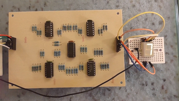
Of digital electronics, a wise man once said that “Every idiot can count to one.” Truer words have rarely been spoken, because at the end of the day, every digital circuit is really just an analog circuit with the interesting bits abstracted away. And to celebrate that way of looking at things, we’re pleased to present this BCD to seven-segment converter that uses no logic chips.

With cheap and easily available chips that perform this exact job, it might seem a little loopy to throw 20 LM324 op-amps at the job. But as [gschmidt958] explains, this is strictly for the challenge, plus it made a nice entry in the recently concluded Op-Amp Challenge contest. His work began in simulation, exploring op-amp versions of the basic logic gates — NAND, AND, OR, and NOT — all of which rely on using the LM324s as comparators. There were real-world curveballs, of course, not least of which was running out of the 10k resistors used for input averaging. Another plot twist was running out of time to order a PCB, which required designing one using MS Paint and etching it at home.

The demo video below shows the circuit at work, taking the BCD output of a 74HC393 counter — clocked by a 555, naturally — and driving a seven-segment LED.  It’s honestly a lot of work for such a simple task, but there’s something satisfying about the whole project. We think [Widlar] would be proud.

Continue reading “Op-Amp Challenge: A Logic-Free BCD”

Custom Circuit Makes For Better Battery Level Display

Isn’t it always the way? There’s a circuit right out of the textbooks, or even a chip designed to do exactly what you want — almost exactly. It’s 80% perfect for your application, and rather than accept that 20%, you decide to start from scratch and design your own solution.

That’s the position [Great Scott!] found himself in with this custom LED battery level indicator. As the video below unfolds we learn that he didn’t start exactly from scratch, though. His first pass was the entirely sensible use of the LM3914 10-LED bar graph driver chip, a device that’s been running VU meters and the like for the better part of four decades. With an internal ladder of comparators and 1-kilohm resistors, the chip lights up the 10 LEDs according to an input voltage relative to an upper and lower limit set by external resistors. Unfortunately, the fixed internal resistors make that a linear scale, which does not match the discharge curve of the battery pack he’s monitoring. So, taking design elements from the LM3914 datasheet, [Great Scott!] rolled his own six-LED display from LM324 quad-op amps. Rather than a fixed resistance for each stage, trimmers let him tweak the curve to match the battery, and now he knows the remaining battery life with greater confidence.

Perhaps the 18650 battery pack [Great Scott!] is building is for the e-bike he has been working on lately. If it is, we’re glad to see that he spot-welded the terminals, unlike a recent e-bike battery pack build that may have some problems down the road.

Continue reading “Custom Circuit Makes For Better Battery Level Display”

Power Wheels engine compartment

Power Wheels Rescued, Restored And Enhanced

It seems power wheels are like LEGO — they’re handed down from generation to generation.  [Nicolas] received his brand-new Peg-Perego Montana power wheels in 1997 as a Christmas present. After sitting in a barn for a decade, and even being involved in a flood, it was time to give it to his godchildren, though not without some restoration and added features. His webpages have a very good write-up, just shy of including schematics, but you’ll find an abbreviated version below.

Continue reading “Power Wheels Rescued, Restored And Enhanced”

A Handful Of Parts Used To Form An Electrocardiogram

minimal-ecg

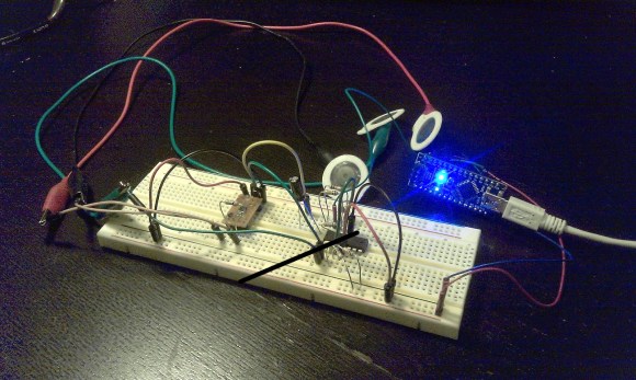
It’s difficult to image a more bare-bones approach to building an ECG. [Raul] used an Arduino nano to collect samples and push them to a computer for graphing.

An Electrocardiogram measures electrical activity around your heart. The white circles above are the sensors which he picked up in a box of fifty for 11 Euros (under $15). Stick them on your skin in just the right places and they’ll report back on what your heart is doing.

He used a AD8221 to amplify the signals. He mentions that this is an ins-amp, not an op-amp. We didn’t find a concise reference explaining what that is. It might be a good topic for the comments section. The signal from that chip feeds into an LM324 op-amp before being dumped into the Arduino.

Simplicity comes at a price. This measures very small electrical impulses and has very little in the way of shielding and filtering. Because of this you may need to do a rain dance, say a prayer, burn a candle, and stick needles into a doll to get a reliable signal on the other end.

Here’s another version that doesn’t require special sensors.

Pulse Oximeter From LM324, LED, And Photodiode

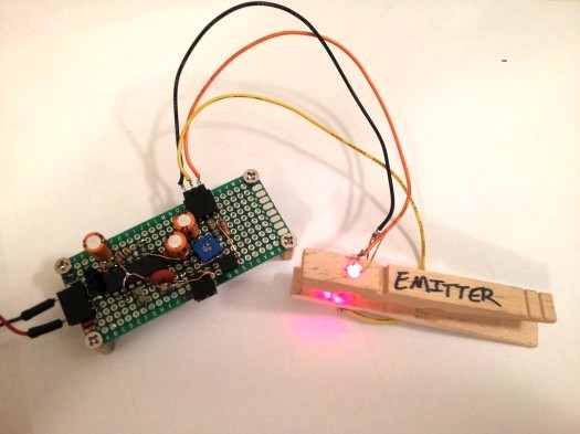
This pulse oximeter is so simple and cheap to build it’s almost criminal. The most obvious way to monitor the output of the sensor is to use an oscilloscope. The poor-man’s stand-in for that is a sound card, which is what [Scott Harden] demonstrates in his write-up.

It uses a concept we’ve seen a few times before. The light from an LED shines through your finger and is measured on the other side by a phototransistor. It’s that light grey plastic thing you see on a patient’s finger when they’re in the hospital. [Scott] went with a common wooden clothes pin as a way to mount and align the sensor with your finger. It is monitored by the simplest of circuits which uses just one chip: an LM324 op-amp. There are three basic stages which he explains well in the video after the jump. The incoming signal is decoupled before being fed to the first amplifier stage. From there it is fed to an adjustable low-pass filter to help eliminate 60Hz noise from AC power in the room. The last stage amplifies the signal again while using another low-pass filter in parallel.

Continue reading “Pulse Oximeter From LM324, LED, And Photodiode”

A Cellphone Based Interactive Voice Response System

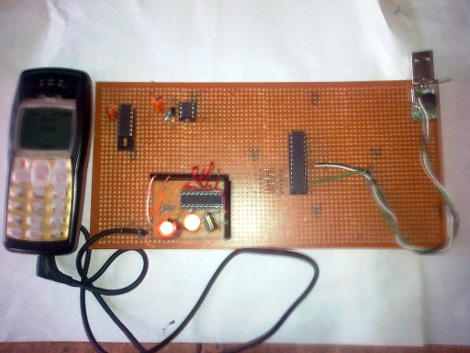
We’re all familiar with IVRS systems that let you access information using a touch-tone telephone. [Achu Wilso] built his own version which uses a cellphone, microcontroller, and computer.

The cellphone is monitored by an LM324 op-amp with an attached 555 timer chip. When a call comes in the voltage on the headphone output goes high, activating the timer circuit. If it goes low and does not go high again for about 25 seconds the call will be ended. Each incoming touch tone acts as a keepalive for the circuit.

An MT8870 DTMF (touch tone) decoder chip monitors the user input. An ATmega8 microcontroller grabs the decoded touch tones from that chip, and pushes them to a PC via USB. The PC-side software is written in Python, using MySQL bindings to access database information. eSpeak, the open source speech synthesizer software is used to read menu and database information back to the caller.

Not a bad little system, we wish there was an audio clip so we could hear it in action.