Reconfigurable FPGA For Single Photon Measurements

Detecting single photons can be seen as the backbone of cutting-edge applications like LiDAR, medical imaging, and secure optical communication. Miss one, and critical information could be lost forever. That’s where FPGA-based instrumentation comes in, delivering picosecond-level precision with zero dead time. If you are intrigued, consider sitting in on the 1-hour webinar that [Dr. Jason Ball], engineer at Liquid Instruments, will host on April 15th. You can read the announcement here.

Before you sign up and move on, we’ll peek into a bit of the matter upfront. The power lies in the hardware’s flexibility and speed. It has the ability to timestamp every photon event with a staggering 10 ps resolution. That’s comparable to measuring the time it takes light to travel just a few millimeters. Unlike traditional photon counters that choke on high event rates, this FPGA-based setup is reconfigurable, tracking up to four events in parallel without missing a beat. From Hanbury-Brown-Twiss experiments to decoding pulse-position modulated (PPM) data, it’s an all-in-one toolkit for photon wranglers. [Jason] will go deeper into the subject and do a few live experiments.

Measuring single photons can be achieved with photomultipliers as well. If exploring the possibilities of FPGA’s is more your thing, consider reading this article.

Smart Ruler Has Many Features

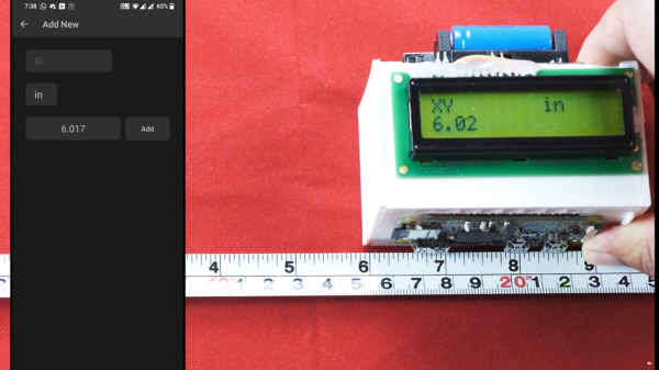
For those of us who remember old ball mice, they were a lot like modern optical mice except that they needed to be cleaned constantly. Having optical mice as a standard way of interacting with a computer is a major improvement over previous eras in computing. With extinction of the ball mouse, there are an uncountable number of cheap optical mice around now which are easy pickings for modern hacking, and this latest project from [Vipul] shows off some of the ways that optical mice can be repurposed by building a digital ruler.

The build seems straightforward on the surface. As the ruler is passed over a surface the device keeps track of exactly how far it has moved, making it an effective and very accurate ruler. To built it, the optical component of a mouse was scavenged and mated directly to a Raspberry Pi Zero W over USB. Originally he intended to use an ESP32 but could not get the USB interface to work. [Vipul] was then able to write some software which can read the information from the mouse’s PCB directly and translate it into human-readable form where it is displayed on a small screen. The entire device is housed in a custom 3D-printed enclosure to wrap everything up, but the build doesn’t stop there though. [Vipul] also leveraged the Bluetooth functionality of the Pi and wrote a smartphone app which can be used to control the ruler as well.

While the device does have some limitations in that it has to make contact with the object being measured across its entire length, there are some situations where we can imagine something like this being extremely useful especially when measuring things that aren’t a straight line. [Vipul] has also made all of the code for this project publicly available for those of us who might have other uses in mind for something like this. We’ve seen optical mice repurposed for all kinds of things in the past, too, including measuring travel distances in autonomous vehicles.

Continue reading “Smart Ruler Has Many Features”

Manual 3D Digitizer Works A Bit Like 3-Dimensional Measuring Tape

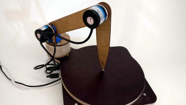
Digitizing an object usually means firing up a CAD program and keeping the calipers handy, or using a 3D scanner to create a point cloud representing an object’s surfaces. [Dzl] took an entirely different approach with his DIY manual 3D digitizer, a laser-cut and 3D printed assembly that uses rotary encoders to create a turntable with an articulated “probe arm” attached.

Each joint of the arm is also an encoder, and by reading the encoder values and applying a bit of trigonometry, the relative position of the arm’s tip can be known at all times. Manually moving the tip of the arm from point to point on an object therefore creates measurements of that object. [Dzl] successfully created a prototype to test the idea, and the project files are available on GitHub.

We remember the earlier version of this project and it’s great to see how it’s been updated with improvements like the addition of a turntable with an encoder. DIY 3D digitizing takes all kinds of approaches, and one example was this unit that used four Raspberry Pi Zeros and four cameras to generate high quality 3D scans.

Circuit VR: Measuring With LTSpice

Usually, with Circuit VR we look at some circuit in detail with simulation — usually LTSpice. This one will be a little meta because I wanted to look at a capability in LTSpice which ironically is very useful, but not often used. Along the way, though, we’ll look at why you get maximum power transfer when your source impedance matches your load impedance. This is something you probably already know about, but it is interesting to look at in simulation if you know how to coax LTSpice — no pun intended — into showing you a meaningful graph.

The circuit is super simple. An AC source and a 50-ohm resistor stand-in for a 40-meter ham transmitter. With 100 volts into a 50-ohm load. So far, so good.

Continue reading “Circuit VR: Measuring With LTSpice”

Arduino And Encoder Form Precision Jig For Cutting And Drilling

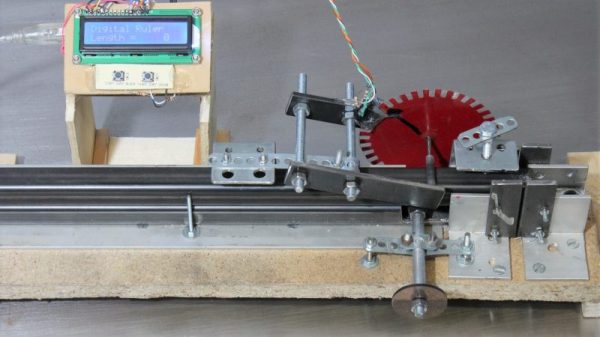
“Measure twice, cut once” is great advice in every aspect of fabrication, but perhaps nowhere is it more important than when building a CNC machine. When precision is the name of the game, you need measuring tools that will give you repeatable results and preferably won’t cost a fortune. That’s the idea behind this Arduino-based measuring jig for fabricating parts for a CNC build.

When it comes to building on the cheap, nobody holds a candle to [HomoFaciens]. We’ve seen his garbage can CNC build and encoders from e-waste and tin cans, all of which gave surprisingly good results despite incorporating such compliant materials as particle board and scraps of plumber’s strapping. Looking to build a more robust machine, he finds himself in need of parts of consistent and accurate lengths, so he built this jig. A sled of particle board and a fence of angle aluminum position the square tube stock, and a roller with a paper encoder wheel bears on the tube under spring pressure. By counting pulses from the optical sensors, he’s able to precisely position the tube in the jig for cutting and drilling operations. See it in action in the video after the break.

If you’ve been following [HomoFaciens], you’ll no doubt see where he’s been going — build a low-end tool, use that to build a better one, and so on. We’re excited to see him moving into more robust materials, but we’ll miss the cardboard and paperclip builds.

Continue reading “Arduino And Encoder Form Precision Jig For Cutting And Drilling”

Using A Lecher Line To Measure High Frequency

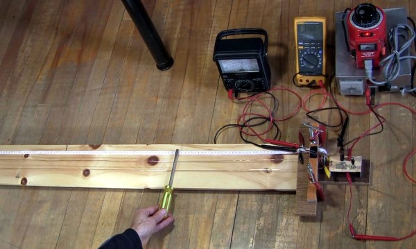
How do you test the oscillator circuit you just made that runs between 200MHz and 380MHz if all you have is a 100MHz oscilloscope, a few multimeters and a DC power supply? One answer is to put away the oscilloscope and use the rest along with a length of wire instead. Form the wire into a Lecher line.

That’s just what I did when I wanted to test my oscillator circuit based around the Mini-Circuits POS-400+ voltage controlled oscillator chip (PDF). I wasn’t going for precision, just verification that the chip works and that my circuit can adjust the frequency. And as you’ll see below, I got a fairly linear graph relating the control voltages to different frequencies.

What follows is a bit about Lecher lines, how I did it, and the results.

Continue reading “Using A Lecher Line To Measure High Frequency”

Probing high voltage

Measuring High Voltage In Millimeters (and Other HV Probe Tricks)

I work a lot with high voltages and others frequently replicate my projects, so I often get asked “What voltage is needed?”. That means I need to be able to measure high voltages. Here’s how I do it using a Fluke high voltage probe as well as my own homemade probe. And what if you don’t have a probe? I have a solution for that too.

How Long Is Your Spark?

The simplest way to measure high voltage is by spark length. If your circuit has a spark gap then when a spark occurs, that’s a short-circuit, dumping all your built up charge. When your spark gap is at the maximum distance at which you get a spark then just before the spark happens is when you have your maximum voltage. During the spark the voltage rapidly goes to zero and depending on your circuit it may start building up again. The voltage before the spark occurred is related to the spark length, which is also the spark gap width.

The oscilloscope photo below shows this changing voltage. This method is good for a rough estimate. I’ll talk about doing more precise measurements when I talk about high voltage probes further down.

Continue reading “Measuring High Voltage In Millimeters (and Other HV Probe Tricks)”