We’re pretty familiar with budget resistor-based bend sensors at this point, but this sensor is in a totally different class. Instead of relying on resistive elements, [Useok Jeong] and [Kyu-Jin Cho] devised a bend sensor that relies on geometric properties of the sensor itself. The result is a higher-fidelity measuring device made from a pretty widely available collection of stock parts.
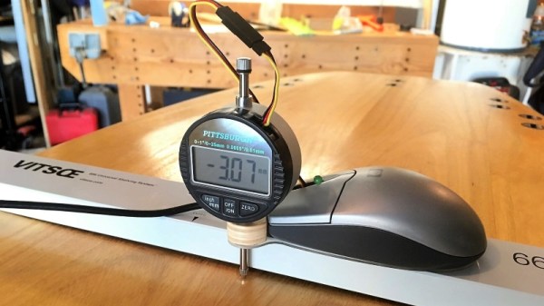
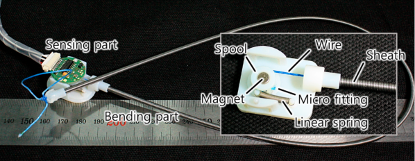
We’ll admit, calling this device a bend sensor might be a bit of a stretch, so let’s dig into some of the operating principles. What we’re actually measuring is the accumulated angle, the sum of all the curvature deformations along the length of the sensing element. The sensor is made of 3 main pieces: an outer extension spring-based wire sheath; a flexible, tensioned inner wire core that’s fixed at one end; and a small displacement sensor that measures the length changes in the wire’s free end. The secret ingredient to making this setup work is a special property of the outer wire sheath or spring guide. Here, the spring guide actually resists being compressed while being bent. Because the inner radius of the bend remains a constant length, the center wire core is forced to elongate. With the excess wire spooled up at the sensor base, we simply measure how much we collected, apply some math, and get a resulting angle! What’s more, the folks behind this trick also demonstrate that the length and angle relationship is linear with an R-square of 0.9969.
One of the best parts about this sensor is how reproducible it seems from from a modest collection of stock parts. Spring guide (aka: extension spring) is available from McMaster-Carr and DR Templeman, and that flexible core might be readily substituted with some wire rope.
It’s not everyday that new topologies for bend sensors pop into the world, let alone linear ones. To learn more, the folks behind the project have kindly made their research paper open access for your afternoon reading enjoyment. (Bring scratch paper!) Finally, if you’re looking for other bend-related sensors, have a look at this multi-bend measurement setup.
Continue reading “Budget-Friendly Bend Sensor Deforms With Precision”