Building The Feynman Motor That Fits Through A Sewing Needle’s Eye

The first attempt at replicating William McLellan's miniature motor. (Credit: Chronova Engineering, YouTube)
The first attempt at replicating William McLellan’s miniature motor. (Credit: Chronova Engineering, YouTube)

How small can an electric motor be without resorting to manufacturing methods like lithography? In a recent video, [Chronova Engineering] on YouTube tries to replicate the 1960 McLellan motor that fulfilled [Richard Feynman]’s challenge requirements. This challenge was part of [Feynman]’s 1959 lecture titled There’s Plenty of Room at the Bottom, on the possibilities of miniaturization. A $1,000 reward was offered for anyone who could build an electric motor that was no larger than 1/64th inch cubed (~0.0625 mm3), with the expectation that new manufacturing methods would be required to manufacture a motor this small.

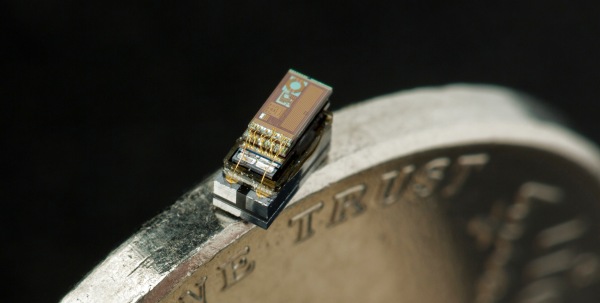
As reported in the December 1960 issue of The Month at Caltech, [William McLellan] walked into [Feynman]’s lab with this tiny marvel that took him 2.5 months of lunch hour breaks to build. Weighing in at 250 micrograms and consisting out of 13 parts, it was constructed using a microscope, a watchmaker’s lathe and a toothpick. Surely replicating this feat would be easy today, right?

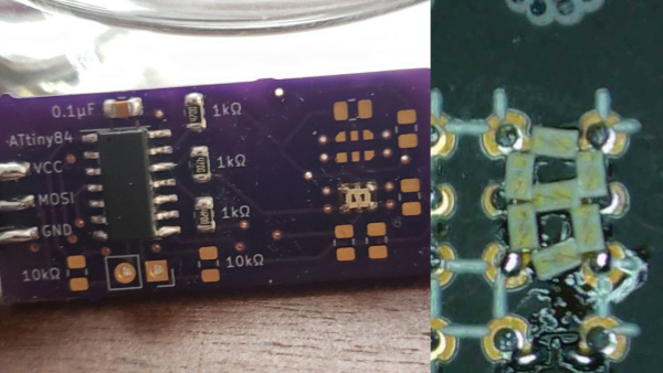
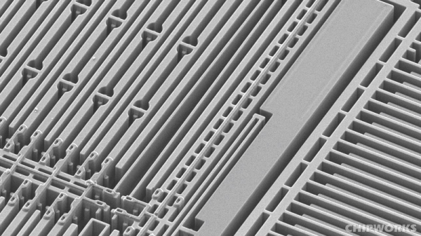
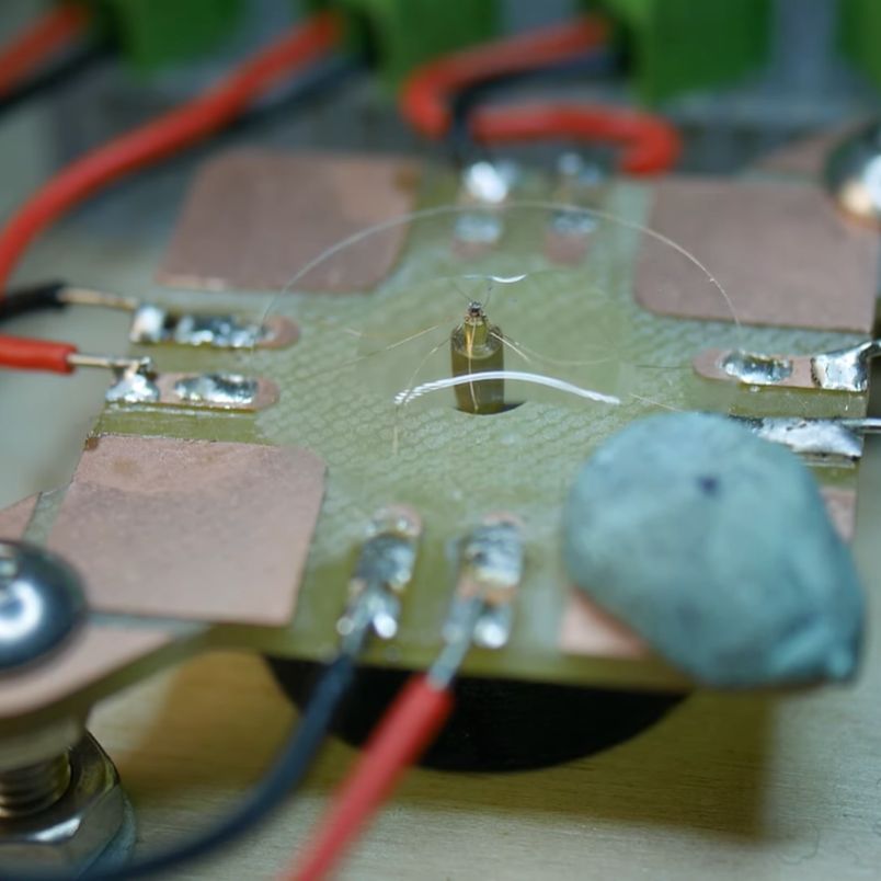
The main challenge is that everything is incredibly small. The rotor shaft is 90 micrometers in diameter, and the four coils require winding incredibly thin wire at scales where typical manufacturing methods do not apply. Suffice it to say that it takes massive amounts of patience, creativity and the best (stereo) microscope you can get, yet even with modern optics and materials this first attempt mostly failed.

At the end we’re left with SEM shots of this replication attempt and an immense amount of respect for the skills of [William McLellan] who made a working version in 1960 using much more basic tools during his lunch breaks.

Thanks to [J. Peterson] for the tip.

Continue reading “Building The Feynman Motor That Fits Through A Sewing Needle’s Eye”

tiny surface mount seven segment display

Nano-Sized 7-Segment LED Display On A Surface Mount Module

Inspired by a prank tweet, [Sam Ettinger] endeavored to create an SMD seven-segment display.  The NanoRaptor NanoSegment implements a panel of seven-segment display modules sized at “0806” each or just a bit wider than a standard 0805 SMD footprint.  Each of the seven segments is a single 0201 LED.  Six I/O lines and three resistors are required to operate each module.

To demonstrate the operation of his tiny display modules, Sam also created the “6Pin 7Seg” development board featuring an ATtiny84 microcontroller coupled to PCB footprints sized to receive the NanoRaptor NanoSegment display modules.  A demonstration of the board counts through digits displayed on one of the tiny seven-segment modules.

Hoping to reduce the module’s interface to two pins, Sam is now experimenting with a seven-segment display on a flex PCB that folds up into a 1208 footprint.  He is attempting to fold the resistors and a ATtiny20 microcontroller into an “origami PCB” configuration.

If these hacks are getting a little too small for your tastes, we’ve got you covered with this giant seven-segment display.


Becky Stern, David Cranor, And A CT Scanner Vs The Oura Ring

If you wonder how it’s possible to fit a fitness tracker into a ring, well, you’re not alone. [Becky Stern] sent one off to get CT scanned, went at it with a rotary tool, and then she made a video about it with [David Cranor]. (Video embedded below.)

While it’s super cool that you can do a teardown without tearing anything down these days — thanks to the CT scan — most of the analysis is done on a cut-up version of the thing through a normal stereo microscope. Still, the ability to then flip over to a 3D CT scan of the thing is nice.

We absolutely concur with [Becky] and [David] that it’s astounding how much was fit into very little space. Somewhere along the way, [David] muses that the electrical, mechanical, and software design teams must have all worked tightly together on this project to pull it off, and it shows. All along, there’s a nice running dialog on how you know what you’re looking at when tearing at a new device, and it’s nice to look over their shoulders.

Then there’s the bit where [Becky] shows you what a lithium-ion battery pack looks like when you cut it in half. She says it was already mostly discharged, and she didn’t burst into flames. But take it easy out there! (Also, make sure you take your hot xylene out on the patio.)

X-ray machines are of course just the coolest thing when doing a teardown. We’ve seen them used from fixing multimeters to simply looking at servo motors.

Continue reading “Becky Stern, David Cranor, And A CT Scanner Vs The Oura Ring”

A close-up view of surface-mount components on a circuit board

Smaller Is Sometimes Better: Why Electronic Components Are So Tiny

Perhaps the second most famous law in electronics after Ohm’s law is Moore’s law: the number of transistors that can be made on an integrated circuit doubles every two years or so. Since the physical size of chips remains roughly the same, this implies that the individual transistors become smaller over time. We’ve come to expect new generations of chips with a smaller feature size to come along at a regular pace, but what exactly is the point of making things smaller? And does smaller always mean better?

Smaller Size Means Better Performance

Over the past century, electronic engineering has improved massively. In the 1920s, a state-of-the-art AM radio contained several vacuum tubes, a few enormous inductors, capacitors and resistors, several dozen meters of wire to act as an antenna, and a big bank of batteries to power the whole thing. Today, you can listen to a dozen music streaming services on a device that fits in your pocket and can do a gazillion more things. But miniaturization is not just done for ease of carrying: it is absolutely necessary to achieve the performance we’ve come to expect of our devices today. Continue reading “Smaller Is Sometimes Better: Why Electronic Components Are So Tiny”

Snails, Sensors, And Smart Dust: The Michigan Micro Mote

If you want to track a snail, you need a tiny instrumentation package. How do you create an entire data acquisition system, including sensors, memory, data processing and a power supply, small enough to fit onto a snail’s shell?

Throughout history, humans have upset many ecosystems around the world by introducing invasive species. Australia’s rabbits are a famous example, but perhaps less well-known are the Giant African land snails (Lissachatina fulica) that were introduced to South Pacific islands in the mid-20th century. Originally intended as a food source (escargot africain, anyone?), they quickly turned out to be horrible pests, devouring local plants and agricultural crops alike.

Not to be deterred, biologists introduced another snail, hoping to kill off the African ones: the Rosy Wolfsnail (Euglandina rosea), native to the Southeastern United States. This predatory snail did not show great interest in the African intruders however, and instead went on to decimate the indigenous snail population, driving dozens of local species into extinction.

A snail with a solar sensor attached to its shell
A Rosy Wolfsnail carrying a light sensing Micro Mote on its back. Source: Cindy S. Bick et al., 2021

One that managed to survive the onslaught is a small white snail called Partula hyalina. Confined to the edges of the tropical forests of Tahiti, biologists hypothesized that it was able to avoid the predators by hiding in sunny places which were too bright for E. rosea. The milky-white shells of P. hyalina supposedly protected them from overheating by reflecting more sunlight than the wolf snails’ orange-brown ones.

This sounds reasonable, but biologists need proof. So a team from the University of Michigan set up an experiment to measure the amount of solar radiation experienced by both snail types. They attached tiny light sensors to the wolf snails’ shells and then released them again. The sensors measured the amount of sunlight seen by the animals and logged this information during a full day. The snails were then caught again and the data retrieved, and the results proved the original hypothesis.

So much for science, but exactly how did they pull this off? Continue reading “Snails, Sensors, And Smart Dust: The Michigan Micro Mote”

Arduboy Gets Even Smaller With New Nano Edition

One of the selling points of the Arduboy is how slim [Kevin Bates] was able to get the Arduino-compatible game system, which is perhaps less surprising when you realize that it originally started out as a design for an electronic business card. But compared to the recently unveiled Nano version, it might as well be the old school “brick” Game Boy.

Now to be clear, [Kevin] isn’t looking to put these into official production. Though it does sound like the bare PCBs might be going up for sale in the near future. This was simply an experiment to see how far he could shrink the core Arduboy hardware while still keeping it not only playable but also code-compatible with the full-size version. While “playable” might be a tad subjective in this case, the video after the break clearly demonstrates that it’s fully functional.

Inside the 3D printed case is the same ATmega32U4 that powers the Arduboy, a 64×32 0.49″ OLED display, and a tiny 25 mAh pouch battery. There’s even a miniature piezo speaker for the bleeps and bloops. All of the pinouts have remained the same so existing code can be moved right over, though the screen is now connected over I2C. [Kevin] has released the schematics for the board in keeping with the general open nature of the Arduboy project, though for now he’s decided to hold onto the board files until it’s clear whether or not there’s a commercial future for the Nano.

We’ve seen attempts to shrink the Arduboy down before, most notably down to the point it could fit inside of a Dreamcast Visual Memory Unit, but the Nano certainly raises (or is that lowers?) the bar considerably.

Continue reading “Arduboy Gets Even Smaller With New Nano Edition”

MEMS: The Biggest Word In Small

What’s tiny and on track to be worth $22 billion dollars by 2018? MEMS (Micro Electrical Mechanical Systems). That’s a catch-all phrase for microscopic devices that have moving parts. Usually, the component sizes range from 0.1 mm to 0.001 mm, which is tiny, indeed. There are some researchers working with even smaller components, sometimes referenced as NEMS (Nano Electrical Mechanical Systems).

Resonant Cantilever by [Pcflet01], CC BY-SA 3.0
MEMS have a wide range of applications including ink jet printers, accelerometers, gyroscopes, microphones, pressure sensors, displays, and more. Many of the sensors in a typical cell phone would not be possible without MEMS. There are many ways that MEMS devices are built, but just to get a flavor, consider the cantilever (see right), one of the most common MEMS constructions.

Continue reading “MEMS: The Biggest Word In Small”