Galactic Dimension – A Supersized DIY Pinball Machine

If you are from the 1960’s or 1970’s we know you would have enjoyed furiously punching the buttons of a pin ball machine back in the day. Installation artist [Niklas Roy] recently revisited this old classic game and built Galactic Dimension – a supersized pinball machine for Phæno – an amazing science center in the German city of Wolfsburg. The science centre was planning a big exhibition featuring thirty beautiful, classic pinball machines loaned from the Pacific Pinball Museum in Alameda, California.

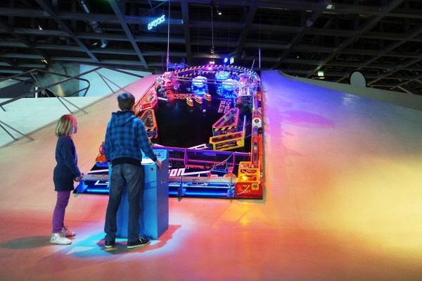
The game machine was built on a steep ramp and has a gigantic play field measuring 3m x 6m (10’x20′). It features Sci-Fi game elements in the play field which blend perfectly with the futuristic building where it is housed. The game elements are built from repurposed everyday items like hair dryers and fans, giving visitors the motivation to build some of their own such contraptions.

The players operate the machine via a control desk, and a giant calculator is used to display the game score. The steep ramp had an incline of almost 30° which meant that he had to use a light ball to be able to propel it around the play field. The main user controls are the two flippers, and building giant ones was a big challenge. Solenoids or coils would not cut the ice, and he settled for pneumatic cylinders – easy to control, powerful, not too loud, and the museum already had a compressed air supply readily available. But it still took him three iterations before he could get it right. The plunger, which initially propels the ball, was built from PVC pipes and a hair dryer. Each play field element was built as a separate module to make assembly and maintenance easier. All featured a 220V AC supply, a sensor (either an IR distance sensor or a light barrier) to detect the ball, and an Arduino. Actuators were built from hair dryers and portable fans. Each of them have their own sound effects too – either a hacked toy or a speaker controlled by the Arduino. After everything was built, taken apart, transported, and reassembled at the site, the Galactic Dimension worked without a glitch, and without releasing any magic smoke. To top it off, Andreas Harre, who’s been the German pinball champion for several years in a row, also played the machine when he visited Phæno – and was totally excited about it!

So if you are in that part of Germany anytime until September, do drop in and try to ring up a big score. For photos of his build log, check out the photo album. There’s also a fairly big block diagram (German) and the Arduino sketches (.zip file), if you’d like to take a stab at building an even bigger pinball machine. Check the video to see the machine in action. And if the name [Niklas] sounds familiar, it is because he loves building installations such as the Forbidden Fruit Machine, the Ball Sucking Machine, and another Ball Sucking Machine.

Continue reading “Galactic Dimension – A Supersized DIY Pinball Machine”

Laser Cutter Exhaust Interlock Is Silly, Educational, Useful

If there’s one maker space that has an excess of mad scientist type hackers, it has to be LVL1 in Louisville, KY. They sure do a lot of crazy stuff, like this simple device to defeat the laser cutter smoke monster. Nobody got the memo about the “simple” part. Instead they created a functional, educational and aesthetically pleasing element for the hackerspace.

LVL1 has a large format laser cutter. Laser cutters emit nasty smoke. Said smoke needs to be vented outside. To do so, it needs to pass through a scrubber/filter so the neighbouring Pigs don’t complain. So they installed a larger, better filter. The Pigs are happy, until the filter gets clogged and the smoke monster decides to escape. Next they install a pressure switch which disables the laser when the filter gets clogged. Laser cutters have a myriad of safety interlocks, so quite often, it isn’t apparent which one caused it to trip. Hence, the Laser Cutter Enable Module – LCEM.

The simple part was to install an indicator that lights up when the pressure switch is enabled, and off when not. But when it’s off, it isn’t clear if the pressure switch is off, or the indicator has failed. Simple, just install a bi-color LED – Red for off, Green for On. But then what about color blind folks who cannot tell the two colors apart? So, finally, two LED’s with clearly labelled text marking them as Enabled and Disabled.

A simple (this time for real) circuit was finally agreed upon. The SPDT contacts of the pressure switch drive the LED in an optoisolator. Its output drives a DPDT relay via a transistor. One set of contacts light up the two indicator LED’s and the other set of contacts goes to the laser cutter enable contacts. Of course, the optoisolator is totally redundant and over kill too – it’s input LED shares the same power supply as the output transistor! Remember the missing memo?

It was time to assemble the circuit. This is where the mad scientist dudes got really creative. On one half of a piece of acrylic, the schematic diagram was etched using the laser. This ensures n00bs get some education. And the remaining half had the circuit laid out in old-skool wire wrap fashion. Holes were drilled and connections were drawn (using the laser, of course) for the various components. Parts were inserted, and wires were soldered to make the connections. The result is what they call the PCB/Mounting Plate/Educational Schematic/Acrylic thing. Of course, exposed connections and wires are no good. So they made a sandwich consisting of a flat acrylic base, and a cut out frame in the middle to accommodate the wire connections and joints. All of this to light up an indicator. Because.

Thanks [JAC_101] from LVL1 for sending in this tip.

If you want to read more about LVL1 shenanigans, check out this post about their Rocketry group, or this post when Hackaday visited LVL1.

IoT Enabled Thomas The Tank Engine

This month the popular “Thomas the Tank Engine” toy celebrated its 70 anniversary. As a fun project, [tinkermax] wanted to bring this traditional toy into the age of IoT, while preserving its physical appearance and simple charm.

He used a model called the “Diesel” which seemed big enough to house the electronics, but proved otherwise once he inspected the innards. He needed to fit in an ESP8266 module, an accelerometer breakout, some discrete parts, a nifty analog multiplexer, and a 14500 3.7V LiPo. Once done, he was able to control its speed remotely over WiFi, with an auto “throttle-boost” that kicks in when the accelerometer senses that the train is going uphill, and has remote monitoring of battery state, engine load, inclination and track vibration – all in real-time using MQTT over WiFi. It’s quite a demonstration of the power of these super-cheap WiFi modules that are powering the current wave of IoT innovation.

The train motor works off a single 1.5V battery, so [tinkermax] tried a couple of boost converters to get the ESP-12 to work. But the modules were a tad bigger, and couldn’t provide the high peak current needed by the ESP-12. So he used a 14500 3.7V LiPo battery instead. A series diode drops the LiPo voltage to a circuit friendly 2.9V ~ 3.6V range. The ADXL345 accelerometer is used to measure “pitch” to detect going up and down a hill, “roll” to check for tilt or tip over and vibration to identify track defects. It communicates with the ESP-12 using a special Lite-SPI library that he wrote.

Two analog measurements are performed. One uses a resistor in series with the PWM driven motor to measure its current, with a low pass filter to smooth out PWM noise. The other is a resistor divider network used to monitor battery voltage. But the ESP-12 has just one ADC channel. Instead of adding another ADC module, [tinkermax] used a neat device – the FSA3157 – which allows two analog inputs to be channeled to a single output much like a SPDT switch. One PWM output is used to control motor speed and a second one to pulse a LED.

The sensor data is streamed 5 times a second over the MQTT protocol to a Raspberry Pi based MQTT broker. Finally, a JavaScript webpage receives the MQTT messages and plots the data graphically. One upgrade he would like to implement is speed measurement, to allow constant speed drive. If you have any ideas on how to extract that information from an accelerometer, chip in with your comments below. Check out his build log in the short video below. And if you’d like to see how all of this can be used in the real world, check this other video where [tinkermax]’s colleague gives a run down about a commercial enterprise IoT cloud platform hooked up to Thomas the Tank Engine.

Continue reading “IoT Enabled Thomas The Tank Engine”

Nixie Clock Uses Ingenious Software RTC

There’s something about Nixie Tube Clocks that keeps drawing hackers to build their own iterations, even if its been done a gazillion times before. Their depleting supply, and the high voltage drivers to control them, makes it all the more interesting. [Pete Mills], a veteran of several interesting projects, many of which we have featured here, is no exception and decided to build his own version of a Nixie Tube Clock, but with several nifty features.

To put it in a nut shell, his Clock uses Nixie tubes for display, has USB serial communication, temperature measurement, AC frequency measurement, time and date keeping with a software based RTC, software driven boost converter for the 175V DC nixie tube supply and a windows app for clock configuration.

The software based time keeping is pretty interesting. It is essentially a method to calibrate the crystal to more closely match real time, and some code to keep track of the time and date.  This obviously leads to a reduction in components and the spin-offs that comes with that; increased reliability, cost reduction, real estate savings. The RTC code can easily be ported to other clock projects irrespective of the display used. Besides keeping track of time and date, it can also account for leap years, and report the day of the week. A zero-crossing detector connected to the low-voltage transformer supply that powers the clock can also be used as an alternative way of keeping time.

When connected to a serial console over UART, the clock can report back many variables depending on the queries it receives. The high voltage DC needed to drive the Nixie tubes is generated using a simple boost converter controlled by the micro controller. An important “gotcha” that [Pete] deduced after blowing off several fuses, was to disconnect the micro controller port connected to the PWM timer and explicitly set it to output low via software. There’s a couple of other issues that he ran into – such as board layout, power supply, incorrect pullups – that make for interesting reading. The clock enclosure is still work in progress, but [Pete] hopes to get it done sometime soon.

He also wrote a Windows application – Nixie Clock Communicator – to help with time setting and calibration. Finally, he describes in detail the process of calibrating the clock’s software based RTC. Based on his calculations, the clock will drift by about 48 seconds over an 8 month period. Since he will be adjusting for DST much sooner than that, his clock ought to be off from correct time by not more than a minute at any given time. Not bad for a clock that does not use a dedicated RTC chip. [Pete] still has some of the prototype boards to give away if someone is interested. If you’d rather build it yourself from scratch, [Pete] has posted the software code, schematics and PCB, and a BoM.

Ducted Fan Drone Uses 1 Rotor For VTOL

Multi-rotor fixed-pitch aircraft – quad, hexa, octa copters – are the current flavor of the season with hobby and amateur flight enthusiasts. The serious aero-modeling folks prefer their variable-pitch, single rotor heli’s. Defense and military folks, on the other hand, opt for a fixed wing UAV design that needs a launch mechanism to get airborne. A different approach to flight is the ducted fan, vertical take-off and landing UAV. [Armin Strobel] has been working on just such a design since 2001. However, it wasn’t until recent advances in rapid-prototyping such as 3D printing and availability of small, powerful and cheap flight controllers that allowed him to make some progress. His Ducted Fan VTOL UAV uses just such recent technologies.

Ducted fan designs can use either swivelling tilt rotors that allow the craft to transition from vertical flight to horizontal, or movable control surfaces to control thrust. The advantage is that a single propeller can be used if the model is not too big. This, in turn, allows the use of internal combustion engines which cannot be used in multi-rotor craft (well, they’ve proven difficult to use thus far).

[Armin] started this project in 2001 in a configuration where the centre of gravity is located beneath trust vectoring, giving the advantage of stability. Since there were no hobby autopilots available at the time, it was only equipped with one gyroscope and a mechanical mixer to control the vehicle around the vertical axis. Unfortunately, the craft was destroyed during the first flight, after having managed a short flight, and he stopped further work on it – until now. To start with, he built his own 3D printer – a delta design with a big build volume of 400mm3. 3D printing allowed him to build a structure which already included all the necessary mount points and supports needed to fix servos and other components. The in-fill feature allowed him to make his structure stiff and lightweight too.

Intending to build his own auto-pilot, he experimented with a BeagleBone Black connected to a micro controller to interface with the sensors and actuators. But he wasn’t too happy with initial results, and instead opted to use the PixHawk PX4 auto-pilot system. The UAV is powered by one 3-cell 3500mAh LiPo. The outside diameter of the duct is 30cm (12”), the height is 55cm (22”) and the take-off weight is about 1.2kg (2.6 pound). It has not yet been flown, since he is still waiting for the electronics to arrive, but some bench tests have been conducted with satisfactory results. In the meantime, he is looking to team up with people who share similar interests, so do get in touch with him if this is something up your alley.

If you want to look at other interesting designs, check this UAV that can autonomously transition from quadcopter flight to that of a fixed-wing aircraft or this VTOL airplane / quadcopter mashup.

Measuring The Accuracy Of A Rubidium Standard

A rubidium standard, or rubidium atomic clock, is a high accuracy frequency and time standard, usually accurate to within a few parts in 1011. This is still several orders of magnitude less than some of the more accurate standards – for example the NIST-F1 has an uncertainty of 5×10-16 (It is expected to neither gain nor lose a second in nearly 100 million years) and the more recent NIST-F2 has an uncertainty of 1×10-16 (It is expected to neither gain nor lose a second in nearly 300 million years). But the Rb standard is comparatively inexpensive, compact, and widely used in TV stations, Mobile phone base stations and GPS systems and is considered as a secondary standard.

[Max Carter] recently came into possession of just such a unit – a Lucent RFG-M-RB that was earlier in use at a mobile phone base station for many years. Obviously, he was interested in finding out if it was really as accurate as it was supposed to be, and built a broadcast-frequency based precision frequency comparator which used a stepper motor to characterise drift.

Compare with WWVB Broadcast

WWVB Receiver
WWVB Receiver

The obvious way of checking would be to use another source with a higher accuracy, such as a caesium clock and do a phase comparison. Since that was not possible, he decided to use NIST’s time/frequency service, broadcasting on 60 kHz – WWVB. He did this because almost 30 years ago, he had built a receiver for WWVB which had since been running continuously in a corner of his shop, with only a minor adjustment since it was built.

comparator1
Comparator Circuit Installed in a Case

His idea was to count and accumulate the phase ‘slips’ generated by comparing the output of the WWVB receiver with the output of the Rb standard using a digital phase comparator. The accuracy of the standard would be calculated as the derivative of N (number of slips) over time. The circuit is a quadrature mixer: it subtracts the frequency of one input from the other and outputs the difference frequency. The phase information is conveyed in the duty cycle of the pulses coming from the two phase comparators. The pulses are integrated and converted to digital logic level by low-pass filter/Schmitt trigger circuits. The quadrature-phased outputs are connected to the stepper motor driver which converts logic level inputs to bi-directional currents in the motor windings. The logic circuit is bread-boarded and along with the motor driver, housed in a computer hard drive enclosure which already had the power supply available.

Continue reading “Measuring The Accuracy Of A Rubidium Standard”

Colorizer For ZX81 Clone

[danjovic] is a vintage computer enthusiast and has several old computers in his collection. Among them are a couple of TK-85 units – a ZX81 clone manufactured by Microdigital Eletronica in Brazil. The TK-85 outputs a monochrome video output. And when [danjovic] acquired a SyncMaster 510 computer monitor, he went about building a circuit to “colorise” the output from the ZX81 clone (Portuguese translation).

The SyncMaster 510 supports 15kHz RGB video refresh rate, so he thought it ought to be easy to hook it up to the TK-85, which internally has the video and composite sync signals available. So, if he could lower the amplitude of the video signal to 0.7Vpp, using resistors, and connect this signal to one of the primary colors on the monitor, for example green, then the screen should have black characters with a green background.

DSCN5584-thumb
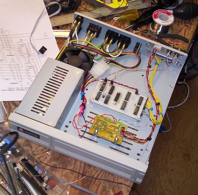
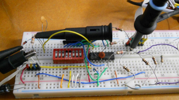
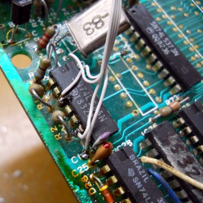
Before he could do any of this, he first had to debug and fix the TK-85 which seemed to be having several age related issues. After swapping out several deteriorating IC sockets, he was able to get it running. He soldered wires directly to one of the logic chips that had the video and sync signals present on them, along with the +5V and GND connections and hooked them up to a breadboard. He then tested his circuit consisting of the TTL multiplexer, DIP switches and resistors. This worked, but not as expected, and after some digging around, he deduced that it was due to the lack of the back porch in the video signal. From Wikipedia, “The back porch is the portion of each scan line between the end (rising edge) of the horizontal sync pulse and the start of active video. It is used to restore the black level (300 mV.) reference in analog video. In signal processing terms, it compensates for the fall time and settling time following the sync pulse.”

To implement the back porch, he referred to an older hack he had come across that involved solving a similar problem in the ZX81. Eventually, it was easily implemented by an RC filter and a diode. With this done, he was now able to select any RGB value for foreground and background colors. Finally, he built a little PCB to house the multiplexer, DIP switches and level shifting resistors. For those interested, he’s also documented his restoration of the TK-85 over a four-part blog post.