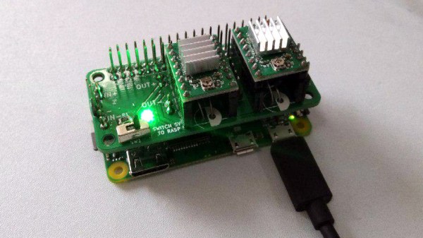
The Raspberry Pi in general (and the Zero W model in particular) are wonderful pieces of hardware, but they’re not entirely plug-and-play when it comes to embedded applications. The user is on the hook for things like providing a regulated power source, an OS, and being mindful of proper shutdown and ESD precautions. Still, the capabilities make it worth considering and [Alpha le ciel] has a project to make implementation easier with the Raspberry Pi Zero W Stepper Motor Module, which is itself part of a larger project plan to make the Pi Zero W into a robust building block for robotic and CNC applications.
[Alpha le ciel] is building this stepper motor module as the first of many Raspberry Pi hats meant to provide the Raspi with the hardware for robotics applications. This module, in particular, features two A4988 stepper motor drivers, a connector for a power supply or battery providing 7-20V, and a buck converter to bring that power down to the 5V needed by the Pi itself. All the relevant pins are broken out onto the Pi’s GPIO header, making this module the simplest way possible to add a pair of motors to a Pi. What does that mean? Printers or self-balancing robots, really whatever you want.
A stepper driver that conforms to the footprint of the Pi Zero is a good start, and the larger concept of creating additional modules is a worthy entry to the Hackaday Prize.


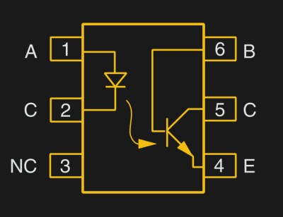 But first a step back. What is an optocoupler anyway? The prototype is an LED and a light-sensitive transistor stuck together in a lightproof case. But there are many choices for the receiver side: photodiodes, BJT phototransistors, MOSFETs, photo-triacs, photo-Darlingtons, and more.