New Part Day: Silent Stepper Motors

Some of the first popular printers that made it into homes and schools were Apple Imagewriters and other deafeningly slow dot matrix printers. Now there’s a laser printer in every office that’s whisper quiet, fast, and produces high-quality output that can’t be matched with dot matrix technology.

In case you haven’t noticed, 3D printers are very slow, very loud, and everyone is looking forward to the day when high-quality 3D objects can be printed in just a few minutes. We’re not at the point where truly silent stepper motors are possible just yet, but with the Trinamic TMC2100, we’re getting there.

Most of the stepper motors you’ll find in RepRaps and other 3D printers are based on the Allegro A498X series of stepper motor drivers, whether they’re on breakout boards like ‘The Pololu‘ or integrated on the control board like the RAMBO. The Trinamic TMC2100 is logic compatible with the A498X, but not pin compatible. For 99% of people, this isn’t an issue: the drivers usually come soldered to a breakout board.

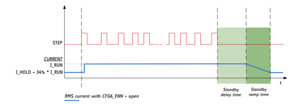
There are a few features that make the Trinamic an interesting chip. The feature that’s getting the most publicity is a mode called stealthChop. When running a motor at medium or low speeds, the motor will be absolutely silent. Yes, this means stepper motor music will soon be a thing of the past.

However, this stealthChop mode drastically reduces the torque a motor can provide. 3D printers throw around relatively heavy axes fairly fast when printing, and this motor driver is only supposed to be used at low or medium velocities.

The spreadCycle feature of the TMC2100 is what you’ll want to use for 3D printers. This mode uses two ‘decay phases’ on each step of a motor to make a more efficient driver. Motors in 3D printers get hot sometimes, especially if they’re running fast. A more efficient driver reduces heat and hopefully leads to more reliable motor control.

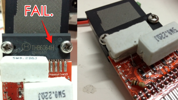
In addition to a few new modes of operation, the TMC2100 has an extremely interesting feature: diagnostics. There are pins specifically dedicated as notification of shorted outputs, high temperatures, and undervolt conditions. This is something that can’t be found with the usual stepper drivers, and it would be great if a feature like this were to ever make its way into a 3D printer controller board. I’m sure I’m not alone in having a collection of fried Pololu drivers, and properly implementing these diagnostic pins in a controller board would have saved those drivers.

These drivers are a little hard to find right now, but Watterott has a few of them already assembled into a Pololu-compatible package. [Thomas Sanladerer] did a great teardown of these drivers, too. You can check out that video below.

Continue reading “New Part Day: Silent Stepper Motors”

Super Nice CNC Router Build Leaves Little To Be Desired

Aluminum CNC Router
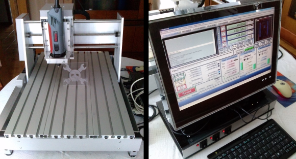
[Enzo] wrote in to tell us about his recently completed CNC Router (translated). This is an excellent high-quality, all-aluminum build with no cut corners. The work envelope is a respectable 340 by 420 mm with 80 mm in the Z direction. Linear ball bearings make for smooth travel and lead screws with both axial and radial bearings give a solid foundation of accurate and repeatable movements.

Aluminum CNC Router

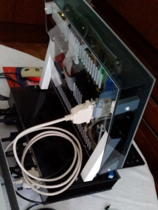
We’ve had a bunch of CNC Router projects on Hackaday in the past, including other nicely made aluminum ones, but [Enzo] is the only one who spent just as much effort on his computer and machine control system as he did on the CNC machine itself. The computer, which is running Windows and Mach3, is an all-in-one style build that starts out with an old LCD screen from a broken laptop. Along with the reused screen, a very small ETX form factor motherboard was stuffed inside a custom made plexiglass enclosure. A Compact Flash card handles the storage requirements.

Underneath the monitor is another great looking custom made enclosure which houses the stepper motor drivers. There are 3 switches on the front panel to send main’s power out to the PC, spindle and an AUX for future use. On the back panel there are D-sub connectors for each stepper motor, the limit switches and the PC connection. Oh yeah, by the way [Enzo] designed his own bipolar motor drivers (translated) and sent the design out for fabrication. These boards use an A4989 IC and mosfets to control the motors. The schematics are on his site in case you’d like to make some yourself.

Continue reading “Super Nice CNC Router Build Leaves Little To Be Desired”

Hackaday Links: June 8, 2014

hackaday-links-chain

Yes, dogfighting with RC planes is cool. You know what’s even cooler? RC jousting. Considering these eight foot long planes are probably made of foam board or Depron, they’ll probably hold up for a fairly long time. The perfect application of RC FPV.

Home automation is the next big thing, apparently, but it’s been around for much longer than iPhones and Bluetooth controllable outlets and smart thermostats. Here’s a home automation system from 1985. Monochrome CRT display panel (with an awesome infrared touch screen setup), a rat’s nest of wiring, and a floor plan drawn in ASCII characters. It’s also Y2K compliant.

Here’s an idea for mobile component storage: bags. Instead of tackle and tool boxes for moving resistors and other components around, [Darcy] is using custom bags made from polyethylene sheets, folded and sealed with an impulse sealer. It’s not ESD safe, but accidentally zapping a LED with an ESD would be impressive.

Need a stepper motor test circuit? Easy, just grab one of those Polulu motor drivers, an ATtiny85, wire it up, and you’re done. Of course then you’re troubled with people on the Internet saying you could have done it with a 555 timer. This one is for them. It’s a 555, some wire, and some solder. Could have done it with discrete transistors, though.

Someone figured out Lego Minifigs can hold iDevice charge cables. +1 for the 1980s spaceman.

Remember that “electronic, color sensing, multicolor pen” idea that went around the Internet a year or so ago? It’s soon to be a Kickstarter, and man, is this thing full of fail. They’re putting an ARM 9 CPU in a pen. A pen with a diameter of 15mm. Does anyone know if an ARM 9 is made in that small of a package? We’ll have a full, “this is a totally unrealistic Kickstarter and you’re all sheep for backing it” post when it finally launches. Also, this.

GRBL Compatible Arduino CNC Shield

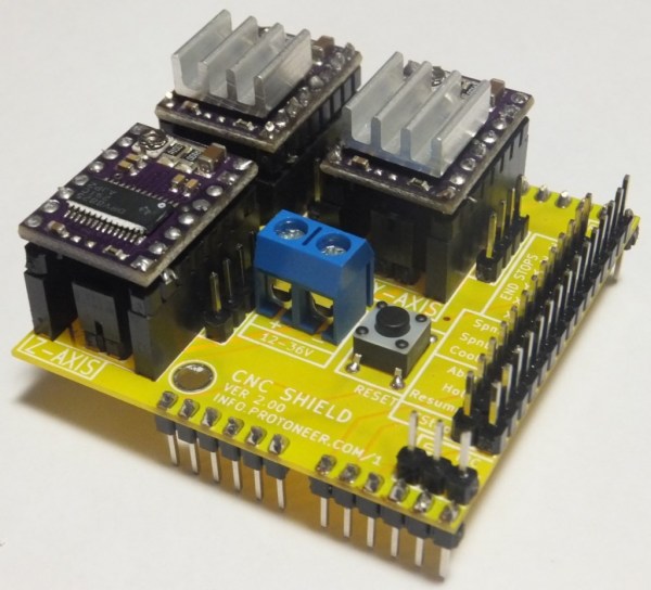
By the time you get to the point in a home CNC build where you’re adding control electronics you may be ready for the simplest means to an end possible. In that case, grab your Arduino and heat up that etching solution to make your own GRBL compatible shield.

This familiar footprint manages to contain everything you need for a three-axis machine. The purple boards slotted into the pairs of SIL headers are Pololu Stepper motor drivers. Going this route makes replacing a burnt out chip as easy as plugging in a new module. The terminal block in the center feeds the higher voltage rail necessary for driving the motors. The DIL header on the right breaks out all of the connections to the limiting switches (two for each axis), spindle and coolant control, as well as three buttons for pause, resume, and abort. There’s even a header for SPI making it easier to add  custom hardware if necessary.

This is a dual-layer board which may not be ideal for your own fabrication process. [Bert Kruger] posted his Gerber files for download if you want to put in a small run with OSH Park or a similar service.


Use Your Ears As An Oscilloscope

image

When work on an engine control circuit [Scott] found himself in need of a way to compare the performance of two control circuits at once. The hobby quality oscilloscope he owns wasn’t up to the task. After thinking about it for a bit he ended up using his ears as the oscilloscope.

The signals he was measuring are well suited for the challenge as they fell within the human range of hearing. He used some wire wrapped around each of the three conductors on the jack of his headphones in order to connect them to a breadboard. Then he simply connected each channel to one of the motor driver circuits, and connected the common ground. Listening to the intonation of the pitches in each ear he was literally able to tune them up.

If he had been looking for a specific frequency he could have used his sound card to take and analyze a sample. But balance was what he needed here and you must admit that this was an easy and clever way to get it!

Qube Robots Use Well-designed Laser-cut Acrylic

These robot cubes, called BOXZ, use an interesting interlocking part design to mount and protect the parts within. But to really make them pop you need to color and apply your own papercraft skins.

The actual hardware is quite simple. They’ve used an Arduino, along with motor driver and Bluetooth shields, to control a set of geared DC motors. There’s a battery pack which holds four AA cells and a pair of servo motors which seem to be there to act as arms. This base can then be adorned with sensors to add functionality (line following, wall following, obstacle avoidance, etc.).

Despite the simple appearance of the cube, the chassis is the most complicated part. It uses sixteen pieces of acrylic, but they may also be hand cut from cardboard by printing out templates and gluing them onto the material. The parts are designed with interlocking tabs which we often see used on laser-cut wooden box parts.

We’ve embedded the video presentation of BOXZ after the break.

Continue reading “Qube Robots Use Well-designed Laser-cut Acrylic”

Doubling Down On Motor Drivers

Motor driver chip too weak for your needs? Just use two of them. That’s the advice which [Starlino] gives. He stacks motor driver chips to product move powerful controllers.

When stacked as shown, the driver combos should be able to drive at 4A. This is partly because he ganged together the outputs in pairs, and also because of the stacking. That’s a lot of juice, but [Starlino] documented his testing stage which shows that they’re up to it. It’s a bit hard to see from this angle, but he is using a serpentine heat sink. It snakes its way between the stack of chips, then over the top chip before folding back and spreading its wings. The motors he’s using have a stall current of 3.7A, and he included resettable fuses graded at a 2A hold current. He’ll be glad to have that extra protection is something goes wrong with the drivers.

[Thanks Roger]