Self balancing wheeled robot with auto-righting arms lofted high

A Self Righting Balancing Robot Configured The Easy Way

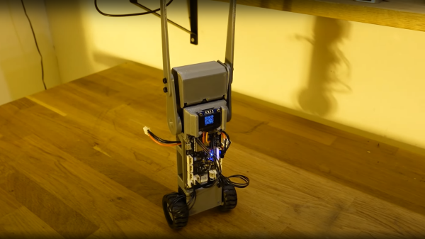
Norwegian electronics hacker [Hans Jørgen] aka [time expander] on YouTube, has a clear interest in robotics, and for his latest effort, decided that it was time to build a custom controller platform. Since [Hans] had a pile of Dynamixel servo motors lying around to test it with, a good first project for the platform was a simple self-balancing wheeled robot. (Video, embedded below)

We say ‘simple’ but that isn’t really the case, as there is a fair bit going on to get this to work. The first problem, is sensing, which was quickly solved with the excellent BMO055 IMU chip. Next, what to do when it falls over? Simply adding some servo-controlled arms, allowed the robot to flip itself back upright. Control is covered with a ESP32-WROOM-32D module from our friends at Espressif, which enables remote firmware uploading over the air (OTA update) as well as parameter tuning. In order to implement the latter, [Hans] chose to use bonjour/mDNS which is an implementation of zero-configuration networking. This gets the ESP32 onto the WiFi, but it isn’t immediately obvious how to connect to it, without a little digging around. To simply connection, [Hans] implemented a dynamic QR code via the connected OLED. This is just one of the those tiny 0.96″ displays that you see touted all over our corners of the internet.

Simply by scanning the QR code with any compatible device to hand brings up a simple configuration web page, allowing one to tweak the PID controller parameters, and get that balancing robot into check. Great stuff!

The PCB was designed in Eagle, firmware for the ESP32 is available, 3D models for the plastic are designed with fusion 360, and [Hans] is even currently working on some preliminary Alexa integration. What a fun project!

All the above, albeit an early cut (look out for bugs!) is available on the project GitHub for your viewing pleasure.

We’re no stranger to self-balancing 3D-printed bots, whilst you’re here, why not checkout A problematic Self-Balancing Sonic the Hedgehog? If wheeled bots aren’t your cup-of-tea, there’s a not-at-all freaky one-legged bouncing bot that may be of interest.

Continue reading “A Self Righting Balancing Robot Configured The Easy Way”

Prepare For Wildfire Season With An Air Quality Monitor

For some reason, wildfire seasons in Australia, North America, and other places around the world seem to happen more and more frequently and with greater and greater fervor. Living in these areas requires special precautions, even for those who live far away from the fires. If you’re not sure if the wildfires are impacting your area or not, one of the tools you can build on your own is an air quality meter like [Costas Vav] shows us in this latest build.

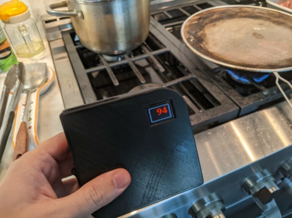
The air quality indicator is based around an Adafruit Feather RP2040 which is in turn based on the 32-bit Cortex M0+ dual core processor. This makes for a quite capable processor in a small package, and helps accomplish one of the design goals of a rapid startup time. Another design goal was to use off-the-shelf components so that anyone could easily build one for themselves, so while the Feather is easily obtained the PMS5003 PM2.5 air quality sensor needed to be as well. From there, all of the components are wrapped up in an easily-printed enclosure and given a small (and also readily-available) OLED screen.

[Costas Vav] has made all of the files needed to build one of these available, from the bill of materials to the software running on the Pi-compatible board to the case designs. It’s a valuable piece of technology to have around even if you don’t live in fire-prone areas. Not only can wildfire smoke travel across entire continents but simple household activities such as cooking (especially with natural gas or propane) can decimate indoor air quality. You can see that for yourself with an army of ESP32-based air quality sensors.

A Hackable Keyboard That Even Has Screens

There are a huge number of available keyboards out in the world these days, catering to all of the plainest and the most advanced desires. However, if you want something that’s just right, sometimes it pays to build your own. [Zach] did just that.

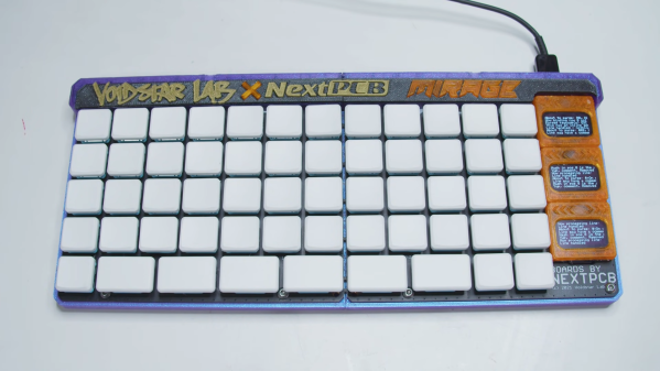
One of the key features of [Zach]’s build is that it diverges away from the Cherry MX switch form factor. The design uses low-profile switches instead, which help with keeping the keyboard low enough to avoid it causing wrist problems. The keyboard also uses IO expanders to hook up all the key switches, helping to reduce the incidence of ghost keys. The board can also be split in half, allowing it to be repurposed as a smaller macropad when desired.

It’s all wrapped up in a cool 3D printed case, and there are even three OLED displays on the right-hand side. They’re soldered to the PCB on special cutouts that allow the displays to flex and trigger tactile switches, acting as giant pressable buttons.

[Zach] does a great job explaining all the nifty engineering decisions he made to cram maximum functionality into the design. We’ve seen some other great DIY ergonomic designs too. Video after the break.

Continue reading “A Hackable Keyboard That Even Has Screens”

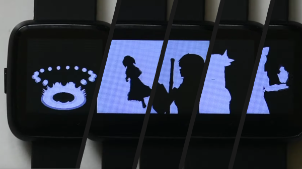
Several frames from Bad Apple

PineTime Smartwatch And Good Code Play Bad Apple

PineTime is the open smartwatch from our friends at Pine64. [TT-392] wanted to prove the hardware can play a full-motion music video, and they are correct, to a point. When you watch the video below, you should notice the monochromatic animation maintaining a healthy framerate, and there lies all the hard work. Without any modifications, video would top out at approximately eight frames per second.

To convert an MP4, you need to break it down into images, which will strip out the sound. Next, you load them into the Linux-only video processor, which looks for clusters of pixels that need changing and ignores the static ones. Relevant pixel selection takes some of the load off the data running to the display and boosts the fps since you don’t waste time reminding it that a block of black pixels should stay the way they are. Lastly, the process will compress everything to fit it into the watch’s onboard memory. Even though it is a few minutes of black and white pictures, compiling can take a couple of hours.

You will need access to the watch’s innards, so hopefully, you have the developer kit or don’t mind cracking the seal. Who are we kidding, you aren’t here for intact warranties. The video resides in the flash chip and you have to transfer blocks one at a time. Bad Apple needs fourteen, so you may want to practice on a shorter video. Lastly, the core memory needs some updating to play correctly. Now you can sit back and…watch.

Pine64 had a rough start with the single-board computers, but they’re earning our trust with things like soldering irons and Google-less Linux mobile phones.

Continue reading “PineTime Smartwatch And Good Code Play Bad Apple”

A homemade seven-segment OLED display

Making OLED Displays In The Home Lab

Just a general observation: when your project’s BOM includes ytterbium metal, chances are pretty good that it’s something interesting. We’d say that making your own OLED displays at home definitely falls into that category.

Of course, the making of organic light-emitting diodes requires more than just a rare-earth metal, not least of which is the experience in the field that [Jeroen Vleggaar] brings to this project. Having worked on OLEDs at Philips for years, [Jeroen] is well-positioned to tackle the complex process, involving things like physical vapor deposition and the organic chemistry of coordinated quinolones. And that’s not to mention the quantum physics of it all, which is nicely summarized in the first ten minutes or so of the video below. From there it’s all about making a couple of OLED displays using photolithography and the aforementioned PVD to build up a sandwich of Alq3, an electroluminescent organic compound, on a substrate of ITO (indium tin oxide) glass. We especially appreciate the use of a resin 3D printer to create the photoresist masks, as well as the details on the PVD process.

The displays themselves look fantastic — at least for a while. The organic segments begin to oxidize rapidly from pinholes in the material; a cleanroom would fix that, but this was just a demonstration, after all. And as a bonus, the blue-green glow of [Jeroen]’s displays reminds us strongly of the replica Apollo DSKY display that [Ben Krasnow] built a while back. Continue reading “Making OLED Displays In The Home Lab”

Why You Can’t Make A Wearable Display With A Transparent OLED

After seeing the cheap transparent OLED displays that have recently hit the market, you might have thought of using them as an affordable way to build your own wearable display. To save you the inevitable disappointment that would result from such a build, [Zack Freedman] took it upon himself to test out the idea, and show why transparent wearable displays are a harder than it looks.

He put together a headband with integrated microcontroller that holds the transparent OLED over the user’s eye, but unfortunately, anything shown on the display ends up being more or less invisible to the wearer. As [Zack] explains in the video after the break, the human eye is physically incapable of focusing on any object at  such a short distance. Contrary to what many people might think, the hard part of wearable displays is not in the display itself, but rather the optics.  For a wearable display to work, all the light beams from the display need to be focused into your eyeball by lenses and or reflectors, without distorting your view of everything beyond the lens. This requires, lightweight and distortion-free collimators and beam splitters, which are expensive and hard to make.

While these transparent OLEDs might not make practical heads-up displays, they are still a cool part for projects like a volumetric display. It’s certainly possible to build your own smart glasses or augmented reality glasses, you just need to focus on getting the optics right.

DIY Handheld Game Puts Its Brains On A Removable Cart

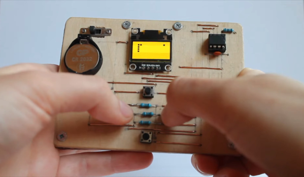
Over the years we’ve seen plenty of homebrew handheld game systems that combine an AVR microcontroller, a few buttons, and an small OLED display. Some of them have even been turned into commercial products, such as the Arduboy. They’re simple, cheap, and with the right software, a lot of fun. But being based on an MCU, most of them share the same limitation of only being able to hold a single game at any one time.

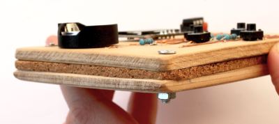
But not the Game Card, by [Dylan Turner]. This handheld was specifically designed so that games could be easily swapped out using physical cartridges. But rather than trying to get the system’s microcontroller to boot code from an external flash chip, the system relocates the MCU to the removable cartridge. That might seem a bit overkill, but given how cheap the ATTINY84A on each cartridge is, it’s not exactly going to break the bank.

With the microcontroller on the cartridge, the only hardware that stays behind on the Game Card is the SSD1306 128×64 OLED display, buttons, and the battery. That means the handheld is effectively non-functional unless a game is slotted in, but that could be said of most early cartridge-based game systems as well. On the other hand, it also opens up the possibility of producing cartridges with more powerful microcontrollers down the line.

Using a different microcontroller for each game is a neat hack, but it’s not the only solution to the problem. We previously saw a community effort to add expandable storage to the Arduboy in the form of a DIY cartridge, which ultimately led to the development of an official flash chip upgrade for the handheld.

Continue reading “DIY Handheld Game Puts Its Brains On A Removable Cart”