This Parametric Project Box Generator Is Super Easy

When it comes to taking an idea from concept to prototype reality, depending on the type of project, there can be quite a few sub-tasks along the way. Take for example, your latest electronic widget design. You’ve finished the schematic, and the PCB layout is a work of art (if you do say so yourself) but having that kicking around on the desk unprotected with wires dangling is not the end game. Now you’ve got to make an enclosure of some kind, and I don’t know about you, but this is the bit where this scribe struggles a little to get something to fit nice. Even if you’ve got the latest 3D printer dialed in to within a gnat’s whisker of perfection, you’ve still got to come up with the design, and those dimensions need to be really accurate. So, for those of us who are great at the PCB, but suck at the enclosure, [Willem Aandewiel] has been busy making the tool just for you, with his PCB-orientated Yet Another Parametric Projectbox generator (YAPP.)

Defining the PCB mounting points w.r.t. the PCB outline

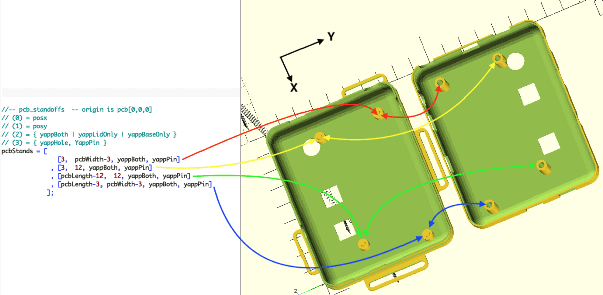
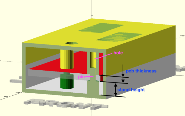
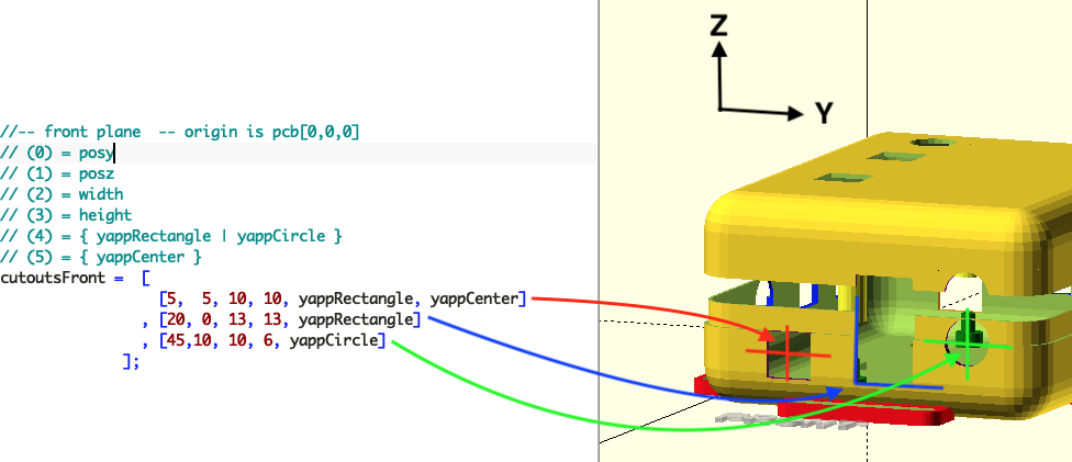
Without hesitation you can head over to the YAPP GitHub, grab that sweet OpenSCAD code, and get cracking with the demos. Provided for your convenience are a number of examples for enclosing some common items, such as Arduinos and ESP32 modules, so you can use those as a springboard to get your own code in place. YAPP works based off the PCB — by specifying programmatically since this is OpenSCAD — outer dimensions, mounting post locations first. Next you define openings in the six faces of the box, and the tool happily spits out a platter with the base and lid ready to drop into Cura (or your slicer of choice) What could be easier?

End face cutouts

And before you start on non-rectangular designs, this is a rectangular box generator for rectangular PCBs. That is all this is designed for, and as far as we can tell, it does that one job well.

Of course, this is by no means the first enclosure generator to grace these pages, far from it. Here’s one for starters. If you’re here for tips to help make better designs, check this out, and finally 3DHubs also has a nice guide for you. Happy printing!

Planar PCB Coils As An Alternative To Winding Transformers

Those readers who have experimented with winding their own inductors will know that it’s not an easy task, and when those inductors are handling high voltages it can be especially tricky to maintain adequate insulation between layers of windings. [Open Frime TV] has a video addressing this in a novel way, by creating the windings for a switch-mode power supply transformer using stacked PCB coils instead of wire (Russian language; you’ll have to enable YouTube’s subtitle auto-translation).

The video below the break makes for a handy primer on PCB coil construction, reminding the viewer that the turns need all to lie in the same direction as well as the importance of insulation between windings. There’s a discussion of the properties of a PCB coil in relation to the switching frequency, and once the transformer has been assembled, we see it hooked up to a power supply board for a test. What happens next may be familiar to seasoned transformer-winders; nothing works, and the transformer gets hot. In making the PCB he’s left some copper on each board which amounts to a shorted turn — cutting these allows the transformer to work perfectly.

This technique might not be the solution to all transformer woes, but makes for an interesting option if your work takes you in the direction of winding transformers. If PCB coils take your interest, how about a Tesla coil using them?

Continue reading “Planar PCB Coils As An Alternative To Winding Transformers”

Ultra Cheap PCB Wrenches Make Perfect Kit Accessory

Let’s make one thing abundantly clear. We do not, under any circumstances, recommend you replace your existing collection of wrenches with ones made out of PCBs. However, as creator [Ben Nyx] explains, they do make for an extremely cheap and lightweight temporary tool that would be perfect for distributing with DIY kits.

This clever open hardware project was spawned by [Ben]’s desire to pack an M3 wrench in with the kits for an ESP32-based kiln controller he’s developing. He was able to find dirt cheap screwdrivers from the usual import sites, but nobody seemed to stock a similarly affordable wrench. He experimented with 3D printing them, but in the end, found the plastic just wasn’t up to the task. Then he wondered how well a tiny wrench cut from a PCB would fare.

The answer, somewhat surprisingly, is pretty well. We wouldn’t advise you try to crank your lug nuts down with one, but for snugging up a couple nuts that hold down a control board, they work a treat. [Ben] came up with a panelized design in KiCad that allows 18 of the little wrenches to get packed into a 100 x 100 mm PCB suitable for production from popular online board houses. Manufactured from standard 1.6 mm FR4, they come out to approximately 10 cents a pop.

Since [Ben] has been kind enough to release his design under the MIT license, you’re free to spin up some of these wrenches either for your own kits or just to toss in the tool bag for emergencies. We’d love to see somebody adapt the design for additional sizes of nuts, or maybe figure out some way to nest them to sneak out a couple extra wrenches per board.

We’ve seen plenty of folks make cheap tools for themselves in the past, but projects that can produce cheap tools in mass quantities is uniquely exciting for a community like ours.

Continue reading “Ultra Cheap PCB Wrenches Make Perfect Kit Accessory”

KiCAD 6.0: What Made It And What Didn’t

I’ve been following the development of KiCAD for a number of years now, and using it as my main electronics CAD package daily for a the last six years or thereabouts, so the release of KiCAD 6.0 is quite exciting to an electronics nerd like me. The release date had been pushed out a bit, as this is such a huge update, and has taken a little longer than anticipated. But, it was finally tagged and pushed out to distribution on Christmas day, with some much deserved fanfare in the usual places.

So now is a good time to look at which features are new in KiCAD 6.0 — actually 6.0.1 is the current release at time of writing due to some bugfixes — and which features originally planned for 6.0 are now being postponed to the 7.0 roadmap and beyond. Continue reading “KiCAD 6.0: What Made It And What Didn’t”

UV Printing PCBs

We always enjoy [Thomas Sanladerer’s] 3D printing videos. But his latest isn’t only about 3D printing. He shows how he uses a DLP printer — which has UV light, after all — to expose PC board blanks with great results. Honestly, once we heard the idea, we immediately saw how that could work it is surprising more people aren’t taking advantage of their DLP printers like that. Of course, [Thomas] does his usual thorough treatment of the topic.

Really, this isn’t exactly 3D printing even though it uses a 3D printer. Exposing boards with UV light and artwork is an old process that has been around for years, usually using transparency film and a UV light source. With a printer, you can create artwork digitally and the UV light source is already there.

Continue reading “UV Printing PCBs”

Implementing A CPU Using 555 Timers And Logic Synthesis

There is many a comment on these here pages along the lines of “Why did you use a microcontroller, when you could just have easily used a 555 timer!” And, yes, we sometimes agree with the sentiment, but when a chance comment seen by Hackaday.io user [Tim Böscke] suggested turning it around and building a microcontroller out of 555 timers, the gauntlet was well and truly thrown down. Now let’s be clear, this is not the first time we’ve come across this idea, there was a breadboard 555 based build ten years ago, but this is the first time we’ve seen it done by leveraging open source synthesis targeting a PCB!

The first logic element was a simple inverter, constructed by tying the TRIGger and THReShold pins together.

LTSpice model of a NAND gate implemented with 555 and diodes

From there it was a simple matter of adding a few diode-resistor networks to the input, to effect a NAND2 gate and a NOR2 gate. Development was speeded up a bit by modeling the logic circuits in LTSpice, to find the best combination of part values. From these simple elements, all further logic functions could be implemented. Next a memory element was needed. As luck would have it, the 555 has a RS flip flop as part of its circuit, fed by dual comparator inputs. All that was needed was to bias the THRS input at Vdd/2 and then feed the data in via a pass transistor, and hey presto! a serviceable, albeit slow latch.

Continue reading “Implementing A CPU Using 555 Timers And Logic Synthesis”

Using Fishing Wire To Hold In Pin Headers Is A Nifty Trick

Working on a breadboard, one can get used to the benefits of being able to readily plug and unplug jumper wires to reconfigure a project. One could only dream of doing so with PCBs, right? Wrong! [Stewart Russell] recently shared a tip on Twitter on how to do just that, with the help of a little fishing wire.

The wire can be neatly threaded through the board to enable quick hookups.

The trick is simple: on any old development board that uses 0.1″ pitch headers, simply weave some fishing line through the plated through-holes in the PCB. Then, regular jumper wires can be inserted just like on a breadboard. The fishing wire has just enough give to allow the jumper wires to be jammed in, holding them steady and in good contact, while still allowing them to be easily removed.

[Hackspace Magazine] has raved about the trick, noting great success using 0.38 mm fishing line. Alternative methods involve using toothpicks, though we suspect solution is likely messier and less reliable.

If you’ve got your own tricks for prototyping quickly using development and breakout boards, be sure to share them below in the comments. Alternatively, send your best stuff to us on the tipsline!