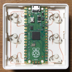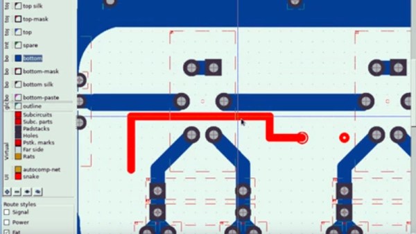
When conversation turns to the older Nokia mobile phones, it’s unlikely to be the long battery life or ability to conjure a signal out of thin air that tickles people’s memory, instead it’s the Snake game built into the stock firmware. Snake was an addictive yet extremely simple game in which a line of pixels — the snake in question — was navigated around the screen to eat the fruit without crashing into walls or itself. As the game progressed the snake grew in length, making it a surprisingly difficult challenge. If you hanker for Snake, as [VK5HSE ] writes, you can now play it in a PCB layout.
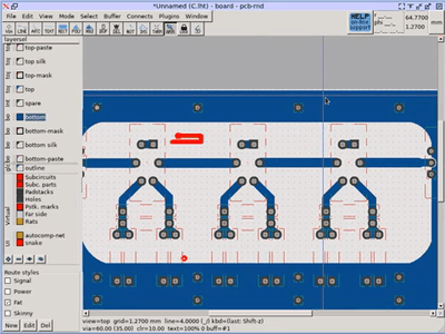 The software in question is PCB-RND, a cross-platform open-source PCB CAD tool, and the game is achieved through the magic of user scripting. Simply download the script, run it in your favourite circuit board, and away you go!
We can’t imagine a productive use for this piece of software, but it wouldn’t surprise us to see a snake slithering into a few boards we feature. It does provide a handy reminder though of the power in your PCB CAD tool’s scripting features, something it’s likely not many of us use to their full potential.
We’ve featured [VK5HSE]’s work with PCB-RND before, in a very useful Eagle import tool.