Patience Beats Rage-Quit In Shattered Xbox Controller Repair

There are negative-one hacks to this project. Someone lost at their game, lost their temper, then raged at their Xbox controller with some horsepower. The result is that [Taylor Burley] gets a free controller with a non-responsive joystick out of the deal, and since he had nothing to lose, he decided to heat up the iron and bring the controller back to life.

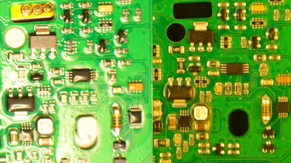
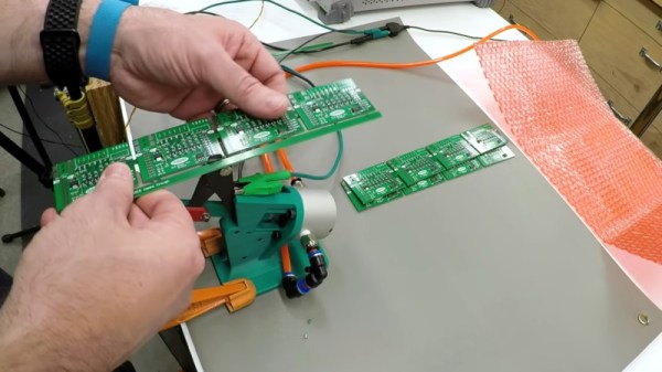
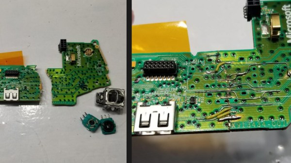
The majority of the project is told in pictures and through the narration in the video below. In removing the joystick, [Taylor] opts for the technique of doping the connections with fresh solder (we assume containing lead for easier melting) before reaching for the desoldering wick. The diagnosis stage is brief because when the joystick lifts away, the PCB falls apart into two separate pieces! The next step was to glue the two halves together with cyanoacrylate to get into the nooks and crannies, then epoxy to provide structure. Solder bridges were not going to jump that gap, so he used 30ga wire and attached it wherever he could scrape away some solder mask. Best of all, it worked when he reattached the joystick. Job well done.

Xbox controllers are not a scarce commodity, so people do not spend their idle hours fixing them, but not many people can claim experience. Maybe someday the stakes will be higher and he will have the courage to repair vintage electronics. We won’t rant on how things aren’t built to last, and how we don’t train people to fix things. Today, we want to focus on someone who used their time to repair and learn.

Continue reading “Patience Beats Rage-Quit In Shattered Xbox Controller Repair”

DIY Relay Module Saves Time

As any programmer could tell you, there’s significant value in automating a process that is performed often enough. The more times that process is used, the more it makes sense to automate it or at least improve its efficiency. This rule isn’t limited to software though; improvements to hardware design can also see improvements in efficiency as well. For that reason, [Hulk] designed a simple relay module in order to cut the amount of time he spends implementing this solution in his various other projects.

While driving a relay with a transistor is something fundamental, this project isn’t really about that per se. It’s about recognizing something that you do too much, and then designing that drudgery out of your projects. [Hulk] was able to design a PCB with 12 modules on it, presumably saving fabrication costs. He can then easily populate them with specific components as soon as he needs one. Another benefit of designing something like this yourself, rather than an off-the-shelf relay module, is that you can do away with any useless features you’ll never need (or add ones that aren’t available in commercial devices).

We can appreciate the efficiency gains this would make for our next project that needs a simple driver for a light, garage door opener, or any other binary electronic device. It can be a hassle to go find the correct transistor and relay, solder it all on the project board, and hope it all works. A pre-made solution solves all these issues, but we do wish the schematics were available to keep us from having to design our own. Driver boards are a pretty common project for all the different types of relays we see around here, so there is probably one available out there.

Perfect Photographs For PCB Reverse Engineering

There’s an unexpected part of hacking that is very difficult to get right, namely photographing printed circuit boards. Everything seems to catch the light, making for a complex dance of manipulating light sources and camera angles. We were thus captured by [Roman Valls]’ budget rig for taking PCB photos that makes ingenious use of roadside trash to achieve a result.

It was inspired by a video featuring a much more accomplished rig, which he set out to emulate for much less outlay. Instead of an expensive lens, he’s using a Nikon camera with its kit lens. And instead of a tripod there’a a scrap drawer salvaged from the roadside and modified to become a camera holder. Lighting is diffused by baking paper, and the result is a rig that can photograph PCBs with neutral lighting and without annoying highlights.

We especially like work that takes junk and makes something useful from it, and though our purpose isn’t in reverse engineering it’s impressive to see how well the technique reveals the traces. We’ll definitely be experimenting with some of the techniques herein, and those lighting tips might also work with the Hackaday ear camera microscope.

Simultaneous Soldering Station

Soldering irons are a personal tool. Some folks need them on the cool side, and some like it hot. Getting it right takes some practice and experience, but when you find a tip and temp that works, you stick with it. [Riccardo Pittini] landed somewhere in the middle with his open-source soldering station, Soldering RT1. When you start it up, it asks what temperature you want, and it heats up. Easy-peasy. When you are ready to get fancy, you can plug in a second iron, run off a car battery, record preset temperatures, limit your duty-cycle, and open a serial connection.

The controller has an Arduino bootloader on a 32u4 processor, so it looks like a ProMicro to your computer. The system works with the RT series of Weller tips, which have a comprehensive lineup. [Riccardo] also recreated SMD tweezers, and you can find everything at his Tindie store.

Soldering has a way of bringing out opinions from novices to masters. If we could interview our younger selves, we’d have a few nuggets of wisdom for those know-it-alls. If ergonomics are your priority, check out TS100 3D-printed cases, which is an excellent iron, in our opinion.

Modular Vibrating ‘Bots Made From PCBs

Printed circuit boards, they’re a medium designed primarily to mount electrical components with the wires themselves places as copper traces on the boards. To accommodate wide range of needs that have arisen over decades, board houses have evolved all manner of advanced techniques in routing and plating. To our benefit, this also makes it possible to leverage PCBs in an entirely artistic way, taking advantage of the highly-optimized manufacturing process. [GeeekClub] did just that, creating awesome vibrating robots out of custom-made PCBs.

The ‘bots come as a single PCB, with the parts snapped out akin to removing parts from sprues in a plastic model kit. They can then be assembled, with a pair of pager vibration motors installed to provide motive power. But really it’s the aesthetic of the boards and not the functionality that make these so incredible.

The design nestles a coin cell in the base of each bot, providing power and using the weight to help keep them upright. There’s a smattering of LEDs on board, and the art style of the ‘bots draws from Hopi Indian, Asian, and South American influences.

Cyphercon 2017 featured these exciting cubic badges, created from PCBs and soldered by hand.
This Star Trek inspired piece shows just how far you can go with the right color soldermask and some creativity.

This “flat-pack” style of PCB design that comes to life with creative use of angles and layers is becoming its own sub-genre of the art. The Star Trek Enterprise inspired build in another great example. We’ve also seen a growing trend of using the PCB as enclosures, take the Cyphercon badge and Queercon badge projects from 2017 as examples. Get yourself up to speed on design techniques for using FR4 as an enclosure from [Voja Antonic’s] in-depth guide.

Hand Depanelizer Gets Pneumatic Upgrade

In high volume production, smaller PCBs are often “panelized” so that multiple copies can be shuffled through assembly as a single piece. Each board is attached to the panel with a few strategically placed tabs, not unlike the sprues in a plastic model kit. If you only have to separate a few boards you can simply cut them with a hand nipper, but when you’re doing hundreds or thousands of boards, it quickly becomes impractical.

Which is where [Clough42] found himself recently. Looking to improve the situation without breaking the bank, he decided to automate his trusty hand-held depanelizer tool. The basic idea was to build an actuator that could stand in for his own hand when operating the tool. He already had a pneumatic cylinder that he could power the device with, he just needed to design it.

In the video below, he walks the viewer though his CAD design process for this project. His first step, which is one that’s often overlooked by new players, is creating digital representations of the hardware he’s using. This allows him to quickly design 3D printed parts that have the proper dimensions and clearances to interface with his real-world components. Remember: it’s a lot easier to adapt your 3D model to the components on hand than the other way around.

With the appropriate valves, hoses, and a foot pedal attached to the pneumatic cylinder, he’s able to operate the cutter completely hands-free. He still has to manually move the panel around, but at least it saves him from the repetitive squeezing motion.

With a tool like this and a custom testing jig, you’ll be producing PCBs like the pros in no time.

Continue reading “Hand Depanelizer Gets Pneumatic Upgrade”

1975 Circuit Board Was A Masterpiece Hidden On Your Wrist

There has been an argument raging for years over whether you should design circuit boards with 45-degree corners or 90-degree corners. Why make them with corners at all? This breathtaking circuit board art is from a digital watch circa 1975.

The Pulsar Calculator Watch was the first of its kind and came along with a stylus to operate the miniscule buttons. The circuit board traces would have been laid out by hand, explaining the gentle curves rather than straight lines. The chip-on-board construction is wild, with the silicon die bonded directly to those traces on multiple chips in this image. There is also a mercury tilt sensor on this model that would have switched the display off when not being held up to view the time (or calculate your tip at the Ritz).

We found working models of this watch for sale online for about $225-350. That’s a steal considering the original list price for these is reported to be $550 ($2600 considering inflation).

The beauty of the PCB artwork is hidden away, not just inside the watch case, but obscured by the plastic battery housing to which those tabs on the right are soldered. Think of how many geeks were lucky enough to have one of these and never realized the beauty within. If you’re looking to unlock more of these hidden masterpieces, check out [Greg Charvat’s] article on collecting and restoring digital wristwatches.

[via Evil Mad Scientist Laboratories link dump]