What’s A Piezo Optomechanical Circuit?

Ever hear of a piezo-optomechanical circuit? We hadn’t either. Let’s break it down. Piezo implies some transducer that converts motion to and from energy. Opto implies light. Mechanical implies…well, mechanics. The device, from National Institute of Standards and Technology (NIST),  converts signals among optical, acoustic and radio waves. They claim a system based on this design could move and store information in future computers.

At the heart of this circuit is an optomechanical cavity, in the form of a suspended nanoscale beam. Within the beam are a series of holes that act as mirrors for very specific photons. The photons bounce back and forth thousands of times before escaping the cavity. Simultaneously, the nanoscale beam confines phonons, that is, mechanical vibrations. The photons and phonons exchange energy. Vibrations of the beam influence the buildup of photons and the photons influence the mechanical vibrations. The strength of this mutual interaction, or coupling, is one of the largest reported for an optomechanical system.

In addition to the cavities, the device includes acoustic waveguides. By channeling phonons into the optomechanical device, the device can manipulate the motion of the nanoscale beam directly and, thus, change the properties of the light trapped in the device.  An “interdigitated transducer” (IDT), which is a type of piezoelectric transducer like the ones used in surface wave devices, allows linking radio frequency electromagnetic waves, light, and acoustic waves.

The work appeared in Nature Photonics and was also the subject of a presentation at the March 2016 meeting of the American Physical Society. We’ve covered piezo transducers before, and while we’ve seen some unusual uses, we’ve never covered anything this exotic.

Hacklet 103 – Piezo Projects

The piezoelectric effect is simple in its rules: Apply mechanical stress to a material and you generate an electric charge. The inverse is also true: Apply a voltage to a material, and it changes shape. This doesn’t work for everything, though. Only certain materials like crystals, some ceramics, and bone have piezoelectric properties. The piezoelectric effect is used quite a bit in electronics, so it’s no surprise that plenty of hacker projects explore this physical phenomena. This week’s Hacklet is all about some of the best projects utilizing the piezoelectric effect on Hackaday.io!
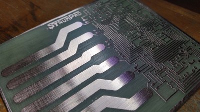
strumWe start with [miro2424] and StrumPad. Strumpad lets you play a MIDI instrument by strumming, just like a guitar. A music keyboard acts as the guitar fretboard here – keys can be pressed to choose notes, but no sound is generated. When the strumpad is strummed, six copper strips act as capacitive sensors. Touching the strips determines which notes will be played. A piezo disc hiding below the circuit board detects how hard the notes have been strummed or tapped. The ATmega328 running the strumpad then passes the velocity and note-on MIDI messages on to a synth.
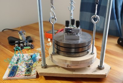
stmNext up is [Dan Berard] with Scanning Tunneling Microscope. Inspired by a project from [John Alexander], [Dan] created his own Scanning Tunneling Microscope (STM). The key to an instrument like this is precise movement. [Dan] achieves that by using a normal piezo disk. These disks are used as speakers and buzzers in everything from smoke detectors to greeting cards, so they’re common and cheap. [Dan] cut his piezo disk electrode into quadrants. Carefully controlling the voltage applied to the quadrants allows [Dan] to move his STM tip in X, Y, and Z. Incredibly, this microscope is able to create images at the atomic scale.
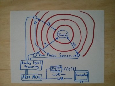
touchboard[Thatcher Chamberlin] is next with Low-Cost Touchscreen Anywhere. [Thatcher] used a trio of Piezo disks to make any flat surface touch sensitive. The three sensors are placed at 3 corners of a rectangle. Touches with the rectangle will create vibrations in the surface that are transmitted to the piezo sensors. By measuring the vibration time of arrival, it should be possible to determine where the surface was touched. This kind of measurement requires a decent processor, so [Thatcher] is using the ARM Cortex-M0 in NXP’s LPC1114FN28. Initial tests were promising, but we haven’t heard much from [Thatcher] on this project. If you see him online, tell him to hurry up! We’re hoping to turn our parking lot into a giant electronic chess board!
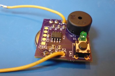
contFinally, we have [Jose Ignacio Romero] with Low Power Continuity Tester. [Jose] used a Piezo element in a slightly more mundane way – as a buzzer. Who needs a whole multimeter when you’re just trying to check continuity on a few circuits? This continuity tester uses a PIC12LF1571 processor to find open and short circuits. The 5 10 bit ADC in the PIC is plenty of resolution for this sort of tester. In fact, [Jose] even included a diode test, which emits a short beep if the leads are placed across a working diode. The PIC processor uses so little power that this tester should run for around 800 hours on a CR2032 watch battery.


If you want to see more piezo projects check out our brand new piezo projects list! If I missed your project, don’t get buzzed! Drop me a message on Hackaday.io, and I’ll add it to the list. That’s it for this week’s Hacklet. As always, see you next week. Same hack time, same hack channel, bringing you the best of Hackaday.io!

Analog Clocks Play Their Own Beat

Play the demo video below and try not to let the rhythm worm its way into your brain. What you’re hearing is the sound of a bunch of clocks, amplified. None of them are keeping wall time, but all of them are playing together.

[Gijs] makes crazy musical instruments. He doesn’t give us much more than a video and a couple schematics for this project, so this one’s still a bit of an enigma, but here’s what we’ve put together.

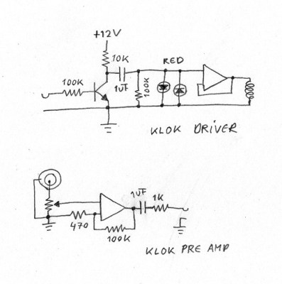
Klok slave unit schematic

The video looks like eight identical version of the same module. The input takes a voltage and converts the rising and falling edges into pulses to drive the coil of an el-cheapo clock. The LEDs pulse as the poles of the clock switch to the incoming beats. The output comes from an amplified piezo sensor stuck on the back of each clock. That is, what you’re hearing is each clock ticking, but amplified. And if you watch the dials spin, it doesn’t look like any of them are telling time.

So far so good, and it matches up with the schematic. But what’s up with that switch on the front? It doesn’t show up anywhere.

And what’s driving the show? [Gijs] tantalizes us with a master clock module (on the same page) that looks like it does keep time, and outputs subdivisions thereof. But that would be too slow to be what’s used in the video. Has he swapped the crystal to make it run faster? It’s a mystery.

Of course, we’d expect no less from the man who mics up a kitchen timer or a gear motor and adds them to his synthesizer rack. We’ve covered a bunch more of [Gijs]’s work in the past, from his video mixers to this hard-drive turned synth oscillator, but this time he’s got us scratching our heads a bit, as well as tapping our feet.

Continue reading “Analog Clocks Play Their Own Beat”

RaspiDrums Uses Expensive Sensors

Piezoelectric sensors are great for monitoring mechanical impacts with a microcontroller. Whether you’re monitoring knocks on a door or watching a heartbeat, they are a cheap way to get the job done. They do have their downsides, though, so when [Jeremy] wanted to build an electronic drum set, he decided to use more expensive accelerometers to measure the percussive impacts instead.

Even though piezo sensors are cheap, they require a lot of work to get them working properly. The ADXL377 3-axis accelerometer that [Jeremy] found requires much less work, plus provides more reliable data due to a 1kHz low-pass filter at the output. In his setup, a Raspberry Pi handles all of the heavy lifting. An ADC on each drum sends data about each impact of the drum, and the Raspberry Pi outputs sound via the native Alsa driver and a USB sound card.

This project goes a long way to show how much simpler a project like this is once you find the right hardware for the job. [Jeremy]’s new electronic drums are very well documented as well if you are curious about using accelerometers on your newest project rather than piezo sensors. And, if you’re into drums be sure to see how you can have drums anywhere, or how you can build your own logic drums.

Continue reading “RaspiDrums Uses Expensive Sensors”

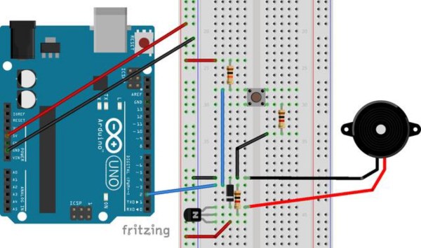
Measuring Heart Rate With A Piezo

Look around for heart rate sensors that interface easily to microcontrollers, and you’ll come up with a few projects that use LEDs and other microcontrollers to do the dirty work of filtering out pulses in a wash of light.

[Thomas] was working on a project that detects if water is flowing through a pipe with a few piezoelectric sensors. Out of curiosity, he taped the sensor to his finger, and to everyone’s surprise, the values his microcontroller were spitting out were an extremely noise-free version of his heart rate.

The piezo in question is a standard, off the shelf module, and adding this to a microcontroller is as easy as putting the piezo on an analog pin. From there, it’s just averaging measurements and extracting a heartbeat from the data.

It’s a much simpler solution to measuring a heart rate, and since two people haven’t heard of this technique, it’s likely a lot more people haven’t heard of this technique either. If you’re looking for an entry to The Hackaday Prize, this would be a great jumping off point for anything in either the fitness or medical domains.

Retrotechtacular: Crystals Go To War

More than one of our readers suggested we highlight this beautifully-shot process documentary about the laborious and precise manufacturing of piezoelectric quartz crystals in the early 1940s. Just a few years later, Bell Labs would perfect a method of growing synthetic crystals, sending droves of brave men and daintily-handed women from the Reeves Sound Laboratories to the unemployment line.

Early radio equipment relied upon tuned or L-C circuits for clocking. These were prone to drift by a few kHz, which prompted the use of crystal oscillators for stable frequencies in the 1920s. The lives of our armed forces and those of our WWII allies depended on reliable communication equipment, so the crystal oscillators they used were top shelf, produced by hand from Brazilian crust.

Continue reading “Retrotechtacular: Crystals Go To War”

Spy Pen

Turning An Ordinary Pen Into A Covert Radio Receiver

[Ben Krasnow’s] latest project will be good for anyone who wants a complicated way to cheat on a test. He’s managed to squeeze a tiny FM radio receiver into a ballpoint pen. He also built his own bone conduction microphone to make covert listening possible. The FM radio receiver is nothing too special. It’s just an off the shelf receiver that is small enough to fit into a fatter pen. The real trick is to figure out a way to listen to the radio in a way that others won’t notice. That’s where the bone conduction microphone comes in.

A normal speaker will vibrate, changing the air pressure around us. When those changes reach our ear drums, we hear sound. A bone conduction mic takes another approach. This type of microphone must be pressed up against a bone in your skull, in this case the teeth. The speaker then vibrates against the jaw and radiates up to the cochlea in the ear. The result is a speaker that is extremely quiet unless it is pressed against your face.

Building the bone conduction mic was pretty simple. [Ben] started with a typical disk-shaped piezoelectric transducer. These devices expand and contract when an alternating current is passed through them at a high enough voltage. He cut the disk into a rectangular shape so that it would fit inside of the clicker on the ballpoint pen. He then encased it in a cylinder of epoxy.

The transducer requires a much higher voltage audio signal than the litter radio normally puts out. To remedy this problem, [Ben] wired up a small impedance matching transformer to increase the voltage. With everything in place, all [Ben] has to do to listen to the radio is chew on the end of his pen. While this technology might help a cheater pass an exam, [Ben] also notes that a less nefarious use of this technology might be to place the speaker inside of the mouthpiece of a CamelBak. This would allow a hiker to listen to music without blocking out the surrounding noise. Continue reading “Turning An Ordinary Pen Into A Covert Radio Receiver”