![]()
[Josh] hit the same issue we’ve faced before: cable modems don’t match a form factor and usually don’t make themselves easy to mount on something. We could complain about routers as well, but at least most of those have keyhole slots so you can hang them on some screws. Inspiration struck and he fabricated his own rack-mount adapter for it. Velcro holds it in place, with a cutout bezel to see the status lights and an added fan to keep things cool.
Here’s a pair of strange but possibly interesting ones that were sent in separately. The first is an analysis of how much energy short-run CNC prototyping consumes versus traditional manufacturing. The other is an article that [Liz] wrote about getting started with CNC mill bits. She says she compiled all that she learned as she was getting started in the field and wants to save others the effort.
This one goes back several years, but who doesn’t love to hear about a voice-controlled wheelchair?
So you can solder QFN parts but you can’t hammer a nail straight into a piece of wood? The answer, friend, is a laser guided hammer. Someone hire this [Andybot] person, because the solution to the problem shows the ability to out-think an interesting dilemma: how do you put a laser in a hammer head and still use it to hit things?
We’ve seen a lot of these long-range WiFi hacks over the years. This one is worth looking at because of the work done to create an outdoor mount that will stand the test of time.
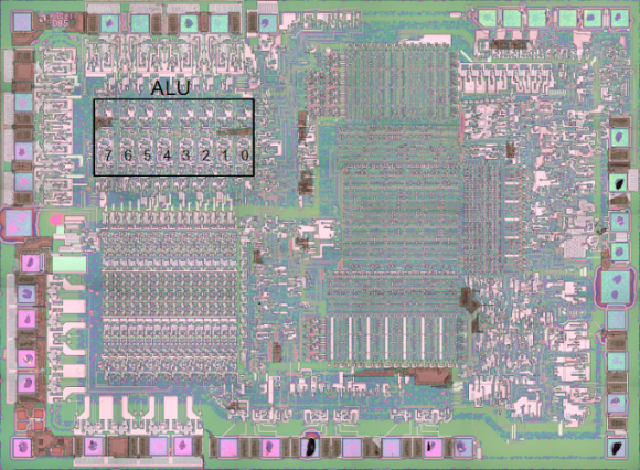
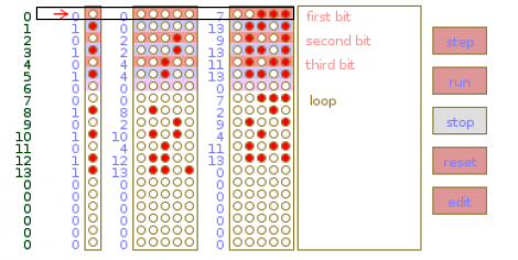
And finally, we’re still really fond of this 2-bit paper processor that helps you wrap your brain around what’s going on with those silicon wafers that rule our everyday lives. [glomCo] liked it as well, and actually coded an emulator so that you can play with it without printing anything out on paper. We think it takes away some of the fun, but what an excellent programming exercise!