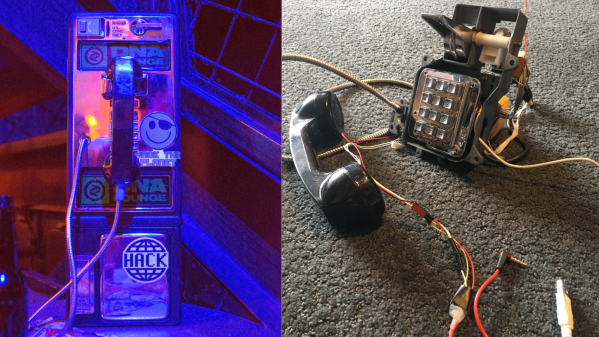
C.H.I.P. Is A Linux Trojan Horse For Nine Bucks

I’m sure you’ve already heard about C.H.I.P, the $9 Linux computer. It is certainly sexy to say nine-bucks but there should really be an asterisk next to that number. If you want things like VGA or HDMI you need an adapter board which adds cost (natively the board only supports composite video output). I also have questions about MSRP once the Kickstarter is fulfilled. But what’s on my mind isn’t cost; this is still going to be in the realm of extremely-inexpensive no matter what shakes out. Instead, I’d like to look at this being the delivery device for wider Linux acceptance.

chip-single-board-computer

The gist of the hardware is a small board with a SoC boasting a 1GHz clock, half a gig of ram, four gigs of flash, one USB, WiFi and Bluetooth. It also has add-ons that make it a handheld and is being promoted as a gaming console. It’s amazing what you get out of these SoC’s for the cost these days, isn’t it?

For at least a decade people have claimed that this is the year of the Linux desktop. That’s not the right way to think. Adults are brand-loyal and business will stick to things that just work. Trying to convert those two examples is a sisyphean effort. But C.H.I.P. is picking up on a movement that started with Raspberry Pi.

These are entry-level computers and a large portion of the user-base will be kids. I haven’t had a hands-on with this new board, but the marketing certainly makes an effort to show how familiar the GUI will be. This is selling Linux and popular packages like LibreOffice without even tell people they’ll be adopting Linux. If the youngest Raspberry Pi users are maturing into their adolescence with C.H.I.P, what will their early adult years look like? At the least, they will not have an ingrained disposition against Open Source Software (unless experiences with Rasbperry Pi, C.H.I.P., and others is negative). At best they’ll fully embrace FOSS, becoming the next generation of code contributors and concept evangelists. Then every year will be the year of the Linux desktop.

Hacklet 46 – ODROID Projects

It seems you can’t mention the Raspberry Pi these days without someone bringing up the Odroid. Named after the combination of Open and Android, the current Odroid brand covers several boards – the U3, the UX3 with its 2 Ghz Samsung quad-core processor, and the C1, which is directly aimed at our favorite fruit pie computer. With all this popularity, one would expect a few awesome projects based around the Odroid machines, and you’d be right! This week’s Hacklet is all about projects using the Odroid on Hackaday.io!

Robbie jrWe start with [herrkami] and CRONUS. Cronus started life as a Robbie Junior, Radio Shack’s re-branded version of Takara Tomy’s Omnibot Jr.  [herrkami] has upgraded Cronus’ brain with an Odroid U3. Cronus can now reliably respond to voice commands thanks to a little help from Google’s speech recognition engine and the accompanying Python API. Cronus is rather conversational as well, all due to the AIML framework. [herrkami] hopes to cut the cord (or WiFi link) once he gets CMU sphinx up and running. Some of [herrkami’s] best work is in his cardboard templates to create a mechanism for turning Cronus’ head. These are some pretty sweet updates for a 1986 vintage robot!


serverNext up is [tlankford01] with Linux Tutorial: Odroid U3 Server w/ Seafile Cloud. [tlankford01] walks us through setting up a file server using the Odroid, a 16 Gigabyte EMMC card, and a hard drive to hold the files. As one might expect, this tutorial covers a LAMP (Linux, Apache, MySQL, PHP) server stack. The 9 project logs take us from a bare microSD card to a full server. The Odroid’s 2 Gigabytes of ram are put to good use running the open source Seafile cloud server package. Tutorials like this deserve lots of love from the Hackaday.io community. Sometimes you just need to get a solid file server up and running. When that happens, this type of project is often just what the doctor ordered! So don’t be a lurker, head over to [tlankford01]’s page and give him a skull!


touch[Victor] gets us one step closer to an Odroid tablet with the HDMI touchscreen. HDMI touchscreen is a project to connect a 7″ 1024 x 600 LCD with a capacitive touchscreen to HDMI based computers. The heart of the project is Texas Instrument’s TFP401 panelbus DVI receiver chip. This chip makes interfacing LCD screens to HDMI or DVI video cards (almost) painless. There still is a bit of X configuration to do to get things running. [Victor] even got his Odroid running in Android with his custom screen setup. Those of us who have spent time in display an input configuration file limbo know that this is no small feat!

htpcFinally we have [darth_llamah] with Odroid-U3 HTPC. [Darth] raided his junkbox and parts drawers to build a solid home theater PC using the Odroid-U2. The U2 is a bit older than the current U3 models, but all [Darth’s] work should apply to any of the Odroid series. An old Itona case provided the frame for this hack, but it took a lot of custom work with plastic and epoxy to make everything fit. [Darth’s] software stack is the popular OpenELEC Linux build. [Darth] even setup a real “soft” power button using an ATtiny85 connected to USB and s Adafruit’s TrinketHidCombo library.

If you want to see all the Odroid projects in one place, check out our new Odroid projects list!

That’s it for this Hacklet, As always, see you next week. Same hack time, same hack channel, bringing you the best of Hackaday.io!

LEDs Strips Tell You The Trains Aren’t Running

[James] is a frequent user of the London Underground, a subway system that is not immune to breakdowns and delays. He wanted a way to easily tell if any of the trains were being disrupted, and thanks to some LEDs, he now has that information available at a glance without having to check a webpage first.

Inspired by the Blinky Tape project at FT Engineering, [James] thought he could use the same strip of addressable LEDs to display information about the tube. A Raspberry Pi B+ gathers data from the London Underground’s TfL API and does a few calculations on the data. If there is a delay, the LEDs in the corresponding section of the strip will pulse, alerting the user to a problem with just a passing glance.

The project is one of many that displays data about the conditions you’ll find when you step outside the house, without having to look at a computer or smartphone. We recently featured an artistic lamp which displays weather forecasts for 12 hours into the future, and there was an umbrella stand which did the same thing. A lot is possible with LEDs and a good API!

Continue reading “LEDs Strips Tell You The Trains Aren’t Running”

Open Source, DIY Soldering Robot

After [Brian] starting selling his own Raspberry Pi expansion boards, he found himself with a need for a robot that could solder 40-pin headers for him. He first did what most people might do by looking up pre-built solutions. Unfortunately everything he found was either too slow, too big, or cost as much as a new car. That’s when he decided to just build his own soldering robot.

The robot looks similar to many 3D printer designs we’ve seen in the past, with several adjustments. The PCBs get mounted to a flat piece of aluminum dubbed the “PCB caddy”. The PCBs are mounted with custom-made pins that thread into the caddy. Once the PCBs are in place, they are clamped down with another small piece of aluminum. A computer slowly moves the caddy in one direction, moving the header’s pins along the path of the soldering irons one row at a time.

The machine has two soldering irons attached, allowing for two pins to be soldered simultaneously. The irons are retracted as the PCB caddy slides into place. They irons are then lowered onto the pins to apply heat. Two extruders then push the perfect amount of solder onto each pin. The solder melts upon contact with the hot pins, just as it would when soldered by hand.

The system was originally designed to be run on a Windows 8.1 tablet computer, but [Brian] found that the system’s internal battery would not charge while also acting like a USB host. Instead, they are running the Windows WPF application on full PC. All of the software and CAD files can be found on [Brian’s] github page. Also be sure to check out the demo video below. Continue reading “Open Source, DIY Soldering Robot”

Hackaday Links Column Banner

Hackaday Links: May 3, 2015

Everybody loves How It’s Made, right? How about 3D printers? The third greatest thing to come out of Canada featured Lulzbot in their most recent episode. It’s eight minutes of fun, but shame the puns weren’t better. Robertson drives and the Avro Arrow, if you’re wondering.

Speaking of 3D printers, a lot of printers are made of aluminum extrusion. Has anyone tried something like this? It’s an idea that’s been around for a while but we can’t seem to find anyone actually using 3D printed extrusion.

CastARs are shipping out, and someone made a holodeck with retroreflective material. It’s an inflatable dome that’s attached to a regular ‘ol tent that works as a positive pressure airlock. If you’re looking to replicate this, try it with hexagons and pentagons. That should be easier than the orange-slice gores.

For some reason we can’t comprehend, USB ports are now power ports. There’s still a lot of stuff that uses 9 and 12V, and for that there’s the USB 912. It’ll work better with one of those USB battery packs.

Want to see what the Raspberry Pi 2 looks like with a Flir? NOQ2 has you covered.

Remember the Speccy? In the manual, there was an exercise left to the reader: reproduce [Mahler]’s first symphony with the BEEP command. It took a Raspberry Pi (only for synchronizing several Speccys), but it’s finally done.

tubenetradio

TubeNetRadio Project Modernizes 1959 Tube Radio

Years ago, [Luk] came across an old tube radio. He’s since wanted to convert it to an internet radio but never really got around to it. Now that we are living in the age when a micro computer can be had for a mere $35, [Luk] decided it was time to finish his long lost project.

He chose a Raspberry Pi for the brains of his project because it is an inexpensive and well documented product perfect for what he wanted to do. [Luk] had a goal, to modify the radio as little as possible in order to get it to play both internet radio and locally stored MP3s. The radio from 1959 is certainly old, but it had a feature you may not expect. It had an AUX input with a separate volume knob out front. As is the radio itself, the input was mono. To connect the Raspberry Pi to the radio, [Luk] had to make an 1/8th inch stereo to banana plug adapter, a great solution that did not require any modification to the original radio.

WiFi is accessed though an off-the-shelf USB wireless module. After evaluating tapping into a 5vdc source somewhere in the radio, it was decided to use a wall wart to power the Raspberry Pi. A plug for the wall wart was spliced in after the radio’s main on/off switch. That way the radio and Raspberry Pi both turn on and off together. There is plenty of room for all of these added components inside the radio’s case.

The RaspPi can be fully controlled over the WiFi network but has a couple buttons wired up to the GPIO pins for limited manual control. The buttons for these controls fit perfectly in the round vent holes in the back panel of the radio’s case. Although the buttons are visible, no permanent modifications had to be made! [Luk] reports that everything works great, as do the original functions of the radio.

robotic dog

Robot K-9 Scares Off The Daleks

[Bithead942’s] love of the ever popular Dr Who series led her to develop a replica of the 4th Doctor’s robotic companion. It’s name is K-9, and was built from scratch in only 4 months. Its shell is made from HPDE – a light and bendable plastic. A custom plastic bender was constructed to get the angles just right, and custom laser cut parts were used in various places.

Its frame consists of aluminum channel, and is packed full of juicy electronics. An arduino with an XBee shield controls the remote voice, frickin’ laser and eye sensors. Another arduino is paired with a motor shield to control the linear actuator for the neck movement. And a Raspberry Pi keeps the LCD screen in order.

We’re not done, folks. Because this puppy is radio controlled, a custom controller is needed. Sparkfun’s Fio paired with another XBee is used along with a 16×2 LCD and various other electronics to keep the robot on an invisible leash.

Be sure to check out the blog site, as it goes into great detail on all the various parts used to construct this complicated but awesome project.