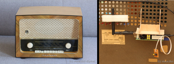
Years ago, [Luk] came across an old tube radio. He’s since wanted to convert it to an internet radio but never really got around to it. Now that we are living in the age when a micro computer can be had for a mere $35, [Luk] decided it was time to finish his long lost project.
He chose a Raspberry Pi for the brains of his project because it is an inexpensive and well documented product perfect for what he wanted to do. [Luk] had a goal, to modify the radio as little as possible in order to get it to play both internet radio and locally stored MP3s. The radio from 1959 is certainly old, but it had a feature you may not expect. It had an AUX input with a separate volume knob out front. As is the radio itself, the input was mono. To connect the Raspberry Pi to the radio, [Luk] had to make an 1/8th inch stereo to banana plug adapter, a great solution that did not require any modification to the original radio.
WiFi is accessed though an off-the-shelf USB wireless module. After evaluating tapping into a 5vdc source somewhere in the radio, it was decided to use a wall wart to power the Raspberry Pi. A plug for the wall wart was spliced in after the radio’s main on/off switch. That way the radio and Raspberry Pi both turn on and off together. There is plenty of room for all of these added components inside the radio’s case.
The RaspPi can be fully controlled over the WiFi network but has a couple buttons wired up to the GPIO pins for limited manual control. The buttons for these controls fit perfectly in the round vent holes in the back panel of the radio’s case. Although the buttons are visible, no permanent modifications had to be made! [Luk] reports that everything works great, as do the original functions of the radio.

 The board uses the