These days, many people love having some lo-fi beats on when they chill and study. This has led to a cottage industry dedicated to producing said beats, and the format continues to grow in popularity. [Nicholas Sherlock] decided to build a custom audio device solely for the delivery of these comfortable tunes.
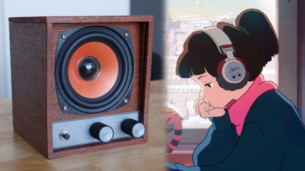
As seen on Reddit, the build relies on a Raspberry Pi 3B, paired with an X400 audio amplifier board and hooked up to a nicely-sized mid-range speaker. The hardware is assembled inside a case printed out of wood-effect PLA filament, giving it a nice old-school home audio aesthetic. As a bonus, the layer lines line up in such a way as to boost the woodgrain effect. Plug it in, and you will be immediately rewarded with lo-fi beats from boot.
 Originally, the system ran a port of the code from lofigenerator.com, which algorithmically creates lo-fi beats from scratch. However, [Nicholas] could not in good conscience share the ported code, and has retooled the system to stream YouTube playlists using command line media player mpv instead. It’s set to stream typical lo-fi playlists, though could be repurposed to target anything on the platform.
It’s a nice build that really suits the lo-fi beats ideal. When you’re trying to study or focus, you don’t want to be mucking around with a YouTube tab open serving as a distraction. Instead, you can simply flick on the Lofipi, and vibe out.
The Raspberry Pi’s cheap price and great internet and media capabilities make it very popular for builds like these. They go some way to recreating the idea of receiving a broadcast, rather than forcing us into choice as per today’s modern on-demand media paradigm. If you’ve got thoughts on this, drop them in the comments, and if you’ve got your own great projects, do drop us a line.