Before the Commodore 64, the IBM PC, and even the Apple I, most computers took input data from a type of non-magnetic storage medium that is rarely used today: the punched card. These pieces of cardstock held programs, data, and pretty much everything used to run computers in the before-time. But with all of that paper floating around, how did a programmer or user keep up with everything? Enter the punch card sorter and [Ken Shirriff[‘s eloquent explanation of how these machines operate.
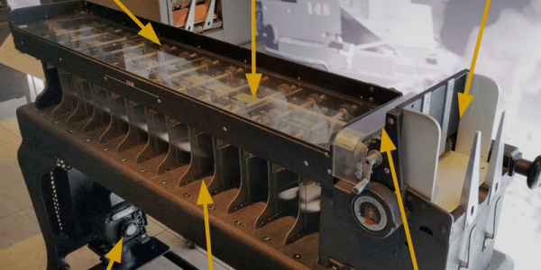
Card sorters work by reading information on the punched card and shuffling the cards into a series of stacks. As [Ken] explains, the cards can be run through the machine multiple times if they need to be sorted into more groups than the machine can manage during one run, using a radix sort algorithm.
The card reader that [Ken] examines in detail uses vacuum tubes and relays to handle the logical operation to handle memory and logic operations. This particular specimen is more than half a century old, rather robust, and a perfect piece for the Computer History Museum in Mountain View.
It’s always interesting to go back and examine (mostly) obsolete technology. There are often some things that get lost in the shuffle (so to speak). Even today, punched cards live on in the automation world, where it’s still an efficient way of programming various robots and other equipment. Another place that it lives on is in voting machines in jurisdictions where physical votes must be cast. Hanging chads, anyone?