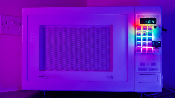
Microwave oven design and manufacturing have been optimized to the point where the once-expensive appliances are now nearly disposable. Despite the economics, though, some people can’t resist fixing stuff, especially when you get a chance to do it in style. Thus we present this microwave repair with its wholly unnecessary yet fabulous adornments.
The beginning of the end for [dekuNukem]’s dirt cheap second-hand microwave started where many of the appliances begin to fail first — the membrane keyboard. Unable to press the buttons reliably anymore, [dekuNukem] worked out the original keypad’s matrix wiring arrangement and whipped up a little keypad from some pushbutton switches and a scrap of perfboard. Wired into the main PCB, it was an effective and cheap solution, if a bit on the artless side.
To perk things up a bit, [dekuNukem] turned to duckyPad, a hot-swappable macropad with mechanical switches and, of course, RGB LEDs. Things got interesting from here; since duckyPad outputs serial data, an adapater was needed inside the microwave. An STM32 microcontroller and a pair of ADG714 analog switches did the trick, with power pulled from the original PCB.
The finished repair is pretty flashy, and [dekuNukem] now has the only microwave in the world with a clicky keypad. And what’s more, it works.
Anyone who enjoys opening up consumer electronics knows iFixit to be a valuable resource, full of reference pictures and repair procedures to help revive devices and keep them out of electronic waste. Champions of reparability, they’ve been watching in dismay as the quest for thinner and lighter devices also made them harder to fix. But they wanted to cheer a bright spot in this bleak landscape: increasing use of stretch-release adhesives.
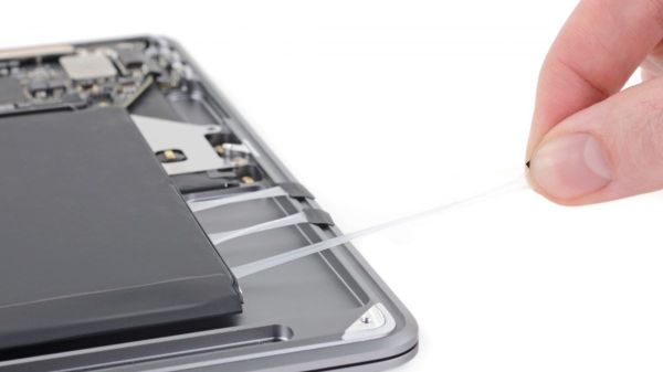
An elegant battery, for a more civilized age.
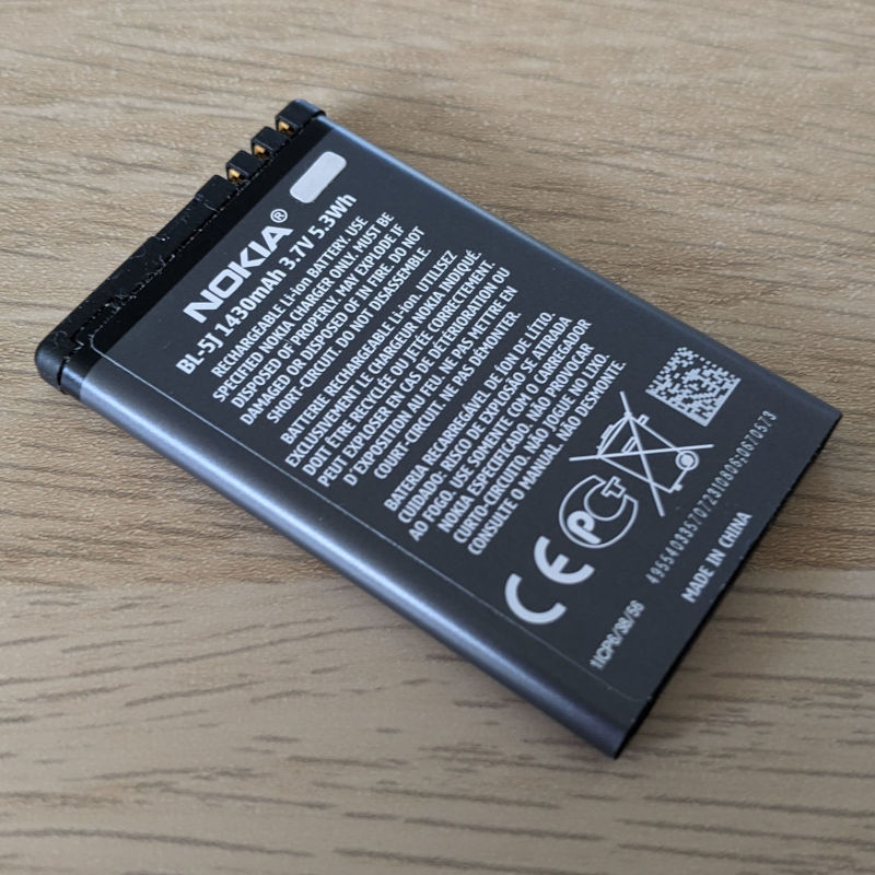
Once upon a time batteries were designed to be user-replaceable. But that required access mechanisms, electrical connectors, and protective shells around fragile battery cells. Eliminating such overhead allowed slimmer devices, but didn’t change the fact that the battery is still likely to need replacement. We thus entered into a dark age where battery pouches were glued into devices and replacement meant fighting clingy blobs and cleaning sticky residue. Something the teardown experts at iFixit are all too familiar with.
This is why they are happy to see pull tabs whenever they peer inside something, for those tabs signify the device was blessed with stretch-release adhesives. All we have to do is apply a firm and steady pull on those tabs to release their hold leaving no residue behind. We get an overview of how this magic works, with the caveat that implementation details are well into the land of patents and trade secrets.
But we do get tips on how to best remove them, and how to reapply new strips, which are important to iFixit’s mission. There’s also a detour into their impact on interior design of the device: the tabs have to be accessible, and they need room to stretch. This isn’t just a concern for design engineers, they also apply to stretch release adhesives sold to consumers. Advertising push by 3M Command and competitors have already begun, reminding people that stretch-release adhesive strips are ideal for temporary holiday decorations. They would also work well to hold batteries in our own projects, even if we aren’t their advertised targets.
Our end-of-year gift-giving traditions will mean a new wave of gadgets. And while not all of them will be easily repairable, we’re happy that this tiny bit of reparability exists. Every bit helps to stem the flow of electronics waste.
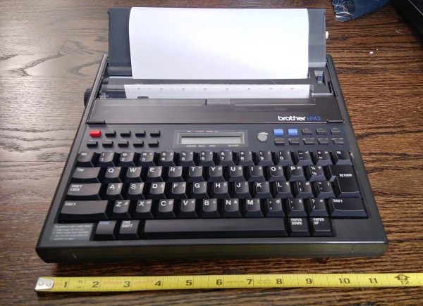
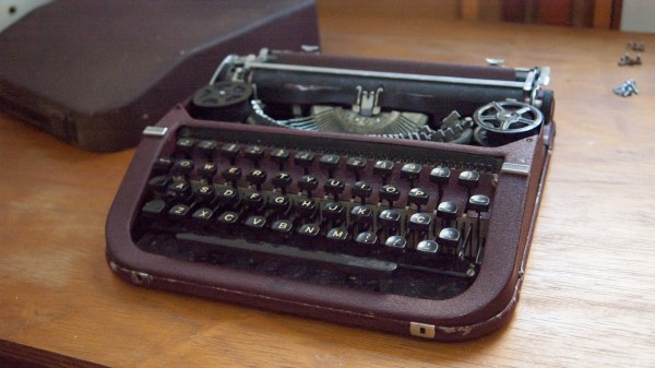
A few months ago, I fell down the internet rabbit hole known as Ted Munk’s typewriter site. I don’t remember if I just saw this Brother EP43 typewriter for sale and searched for information about them, or went looking for one after reading about them. Either way, the result is the same — I gained a typewriter.
Now I’m not really a typewriter collector or anything, and this is my first word processor typewriter. When it arrived from Goodwill, I anxiously popped four ‘C’ cells in and hoped for the best. It made a print head noise, so that was a good sign. But almost immediately after that, there was a BANG! and then a puff of smoke wafted out from the innards. My tiny typewriter was toast. Continue reading “Clacker Hacker: Popping A Cap In A Brother EP43 Thermal Typewriter”→
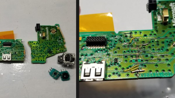
There are negative-one hacks to this project. Someone lost at their game, lost their temper, then raged at their Xbox controller with some horsepower. The result is that [Taylor Burley] gets a free controller with a non-responsive joystick out of the deal, and since he had nothing to lose, he decided to heat up the iron and bring the controller back to life.
The majority of the project is told in pictures and through the narration in the video below. In removing the joystick, [Taylor] opts for the technique of doping the connections with fresh solder (we assume containing lead for easier melting) before reaching for the desoldering wick. The diagnosis stage is brief because when the joystick lifts away, the PCB falls apart into two separate pieces! The next step was to glue the two halves together with cyanoacrylate to get into the nooks and crannies, then epoxy to provide structure. Solder bridges were not going to jump that gap, so he used 30ga wire and attached it wherever he could scrape away some solder mask. Best of all, it worked when he reattached the joystick. Job well done.
Xbox controllers are not a scarce commodity, so people do not spend their idle hours fixing them, but not many people can claim experience. Maybe someday the stakes will be higher and he will have the courage to repair vintage electronics. We won’t rant on how things aren’t built to last, and how we don’t train people to fix things. Today, we want to focus on someone who used their time to repair and learn.
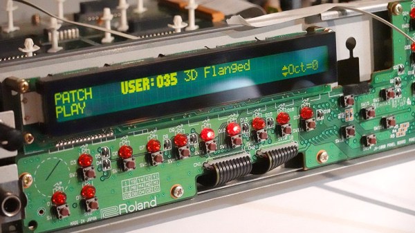
[Mitxela]’s repair of a Roland JV-1080 (a rack-mounted 90s-era synthesizer) sounds simple: replace a broken rotary encoder on the front panel. It turned out to be anything but simple, since the part in question is not today’s idea of a standard rotary encoder at all. The JV-1080 uses some kind of rotary pulse switch, which has three outputs (one for each direction, and one for pushing the knob in like a button.) Turn the knob in one direction, and one of the output wires is briefly shorted to ground with every detent. Turn it the other way, and the same happens on the other output wire. This is the part that needed a replacement.
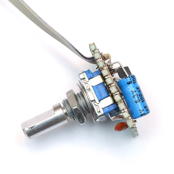
The finished unit uses a modern rotary encoder and microcontroller in place of the original part, and implements a few tricks to power it.
Rather than track down a source for the broken part, [Mitxela] opted to replace it with a modern rotary encoder combined with an ATtiny85 microcontroller to make it act like something the JV-1080 understands and expects. There was an additional wrinkle, however. The original rotary pulse switch is an entirely passive device, and lives at the end of a four-conductor cable with no power provided on it. How could the ATtiny85 be powered without resorting to running a wire to a DC voltage supply somewhere? Success was had, but it did take some finessing.
For the power, it turns out that the signal wires are weakly pulled up to +5 V and [Mitxela] used that for a power supply to the microcontroller. Still, by itself that wasn’t enough, because the ATtiny85 can easily consume more current than the weak pullups can source. We really recommend reading all the details in [Mitxela]’s writeup, but the short version is that the ATtiny85 does two things.
First, it minimizes its power usage by spending most of its time in sleep mode (consuming barely any power at all) and uses an interrupt to wake up just long enough to handle knob activity. Second, the trickle of power from the weak pullups doesn’t feed the ATtiny directly. It charges a 100 uF capacitor through a diode, and that is what keeps the microcontroller from browning out during its brief spurts of activity. Even better, after browsing the datasheet for the ATtiny, [Mitxela] saw it was possible to use the built-in ESD protection diodes for this purpose instead of adding a separate component.
It’s a neat trick and makes for a very compact package. Visit the project’s GitHub repository to dive into the nitty gritty. In the end, a single assembly at the end of a 4-wire connector acts just like the original passive component, no extra wires or hardware modifications needed.
When opening older hardware it’s never quite certain what will be found on the inside. But at least [Mitxela]’s repair duties on this synth didn’t end up with him tripping out on LSD.
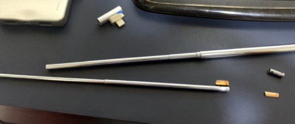
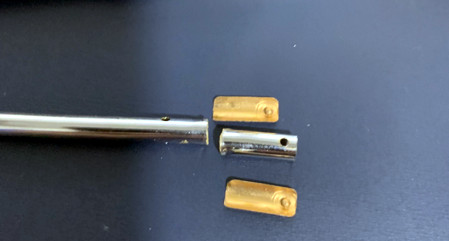
Whether it was as an impulsive youth or an impatient adult, there’s probably few among us who haven’t broken a telescopic antenna or two over the years. It doesn’t take much to put a bend in the thin walled tubing, and after that, all bets are off. So [The Amateur Engineer] couldn’t really be too upset when his son snapped the antenna off the transmitter of an old RC truck. Instead, he decided to take it apart and see how it could be repaired.
Taking a thin screwdriver to the antenna’s bottom most segment, he was able to widen up the opening enough to remove the upper sections as well as recover the broken piece and copper locking plates. He cut out the damaged area and drilled new holes for the pins on the copper plates to fit into. Inserting the repaired section back into the lowest segment was no problem, but he says it took a little trial and error before he was able to roll the edge over enough to keep the antenna from falling apart.
Buying a replacement would certainly have been easier, but as the radios in our devices have moved into the higher frequencies, these collapsible antennas have become a bit harder to come by. Modern RC vehicles operate on 2.4 GHz, so they don’t need the long antennas that the older 27 MHz systems utilized. [The Amateur Engineer] did find a few direct replacements online, but none for a price he was willing to pay.
We might have used the broken transmitter as an excuse to switch the RC vehicle over to WiFi control, but we appreciate [The Amateur Engineer] showing how this type of antenna can be disassembled and repaired if necessary.
You may find yourself living in interesting times. The world we knew two months ago is gone, and there is time enough at last, to finally go through those projects we’ve been putting off for one reason or another. Today, I wanted to explore and possibly repair an old unidentified typewriter that belonged to my late aunt for many decades.
A small disclaimer though, I am not an avid typewriter collector or connoisseur. I enjoy looking at them and using them, but by no stretch of the imagination I want to claim to be an expert in their history or inner workings — I’m a hacker after all. What follows is a layman’s adventure into her first typewriter repair, an exciting tale that explores typewriter anatomy and troubleshooting. Let’s dig in.