There’s plenty of debate about drop-in LED headlight bulbs, especially when they’re used with older reflector housings that were designed for halogen bulbs. Whether or not you personally feel the ultra-bright lights are a nuisance, or even dangerous, one thing we can all agree on is that they’re clearly the result of some impressive engineering.
Which is why we were fascinated to see the teardown [TechChick] did on a “Ultra 2 LED” retrofit from GTR Lighting. Apparently one of the diodes was failing, and as part of the warranty replacement process, she was informed she had to make it completely inoperable. Sounds like a teardown dream come true. If a manufacturer ever told us we needed to take something apart with extreme prejudice and provide photographic evidence that the deed was done, we’d be all too happy to oblige.
 The driver itself ended up being completely filled with potting compound, so she doesn’t spend much time there. Some will no doubt be annoyed that [TechChick] didn’t break out the small pointy implements and dig all that compound out, but we all pretty much know what to expect when it comes to driving LEDs. The real interesting bit is the bulb itself.
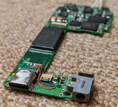
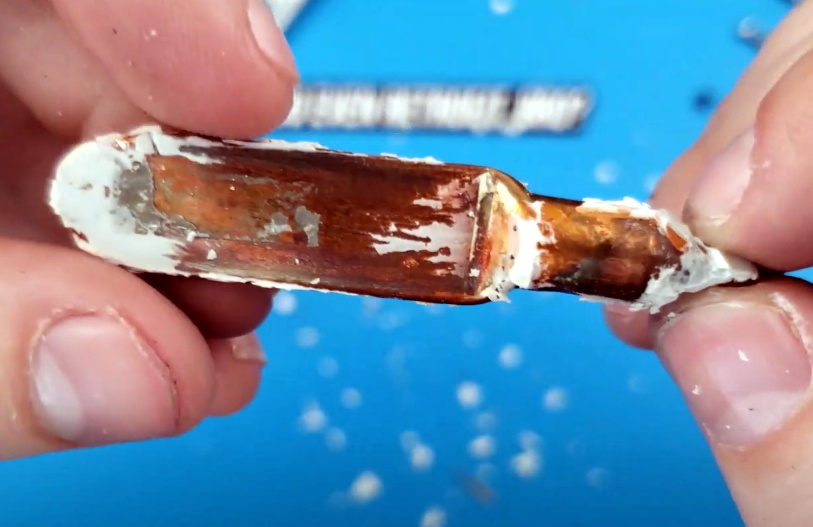
As is common with these high-output automotive LEDs, the Ultra 2 is actively cooled with a small fan that’s actually enclosed within the heatsink. With the fan and the two-piece heatsink removed, she’s able to access the LED module itself. Here, two PCBs are sandwiched back to back with a hollow copper chamber that leads out of the rear of the module. When [TechChick] cut into the copper she said she heard a hiss, and assumed it was some kind of liquid cooling device. Specifically we think it’s a vapor chamber that’s being used to pull heat away from the diodes and into the heatsink at the rear of the module, which speaks to the advanced technology that makes these bulbs possible.
While laser headlights are arguably the future of automotive lighting, it’s going to be quite some time before they trickle down to those of us that don’t own supercars. Until then, when used responsibly, these LED retrofits can inject a bit of cutting-edge tech into your old beater without breaking the bank.
Continue reading “Exploring An Aftermarket LED Headlight Retrofit Kit”