The Pi Zero is a great piece of hardware, even if you’re not designing another USB hub for it. [Marcel] wanted to control a few RGB LED strips from his phone, and while there are a lot of fancy ways you can do this, all it really takes is a Pi Zero and a few parts that are probably already banging around your parts drawers.
This isn’t a project to control individually addressable RGB LEDs such as NeoPixels, WS2812s, or APA102 LEDs. This is just a project to control RGB LEDs with five four connectors: red, green, blue, power, and or ground. These are the simplest RGB LEDs you can get, and sometimes they’re good enough and cheap enough to be the perfect solution to multi-colored blinkies in a project.
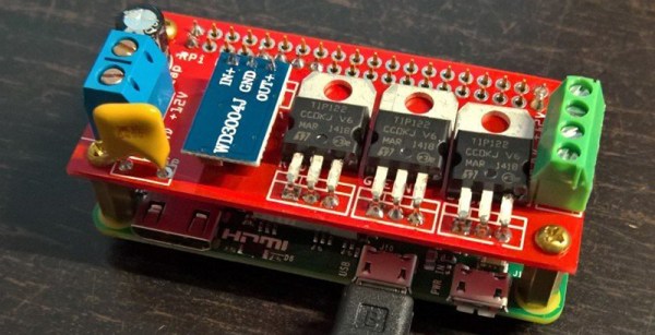
Because these RGB LEDs are simple, that means controlling them is very easy. [Marcel] is just connecting a transistor to three of the PWM pins on the Pi and using a TIP122 transistor to drive the red, green, and blue LEDs. You’ve got to love those TIPs package parts!
Control of the LEDs is accomplished through lighttpd. This does mean a USB WiFi dongle is required to control the LEDs over the Internet, but it is so far the simplest way we’ve seen to add multicolor blinkies to the web.

The Raspberry Pi Zero contest is presented by Hackaday and Adafruit. Prizes include Raspberry Pi Zeros from Adafruit and gift cards to The Hackaday Store!
See All the Entries || Enter Your Project Now!

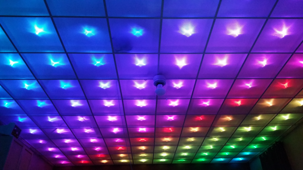
 Disco Floor’s are passé. [dennis1a4] turned them upside down and built an awesome
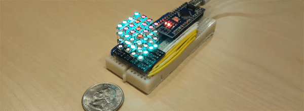
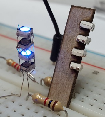
  The hard part was wiring up all of the 160 LED pixels. Instead of mounting the 5050 SMD LED’s on PCBs, [dennis1a4] wired them all up “dead bug” style. Each pixel has one LED, a 100nF decoupling capacitor, and 91 ohm resistors in series with the Data In and Data Out pins – these apparently help prevent ‘ringing’ on the data bus. Check the video for his radical soldering method. Each SMD LED was clamped in a machine shop vice, and the other three parts with their leads preformed were soldered directly to the LED pins.