Fail Of The Week: Bright Idea For LED Signs Goes Bad

Typically when we select a project for “Fail to the Week” honors, it’s because something went wrong with the technology of the project. But the tech of [Leo Fernekes]’ innovative LED sign system was never the problem; it was the realities of scaling up to production as well as the broken patent process that put a nail in this promising project’s coffin, which [Leo] sums up succinctly as “The Inventor’s Paradox” in the video below.

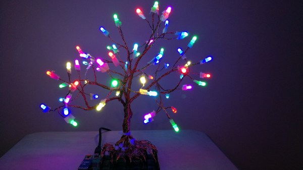
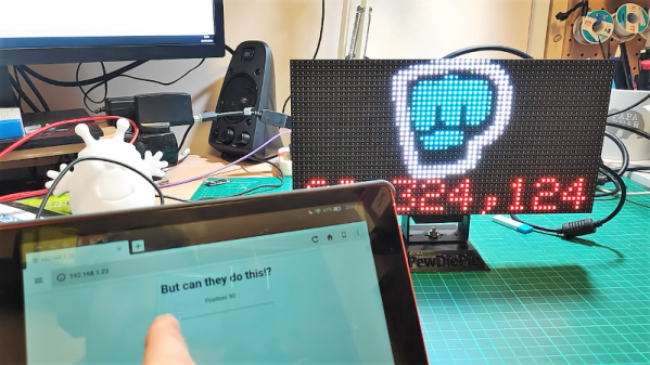
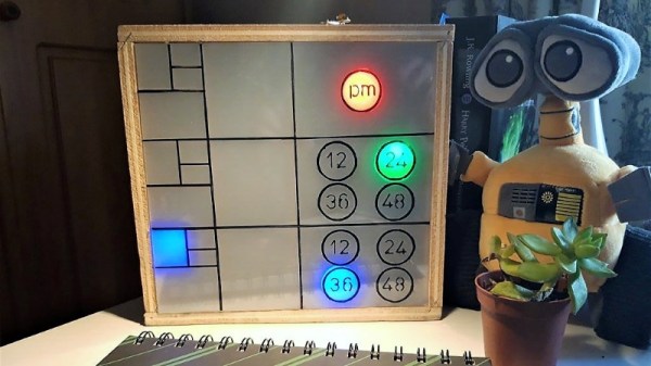
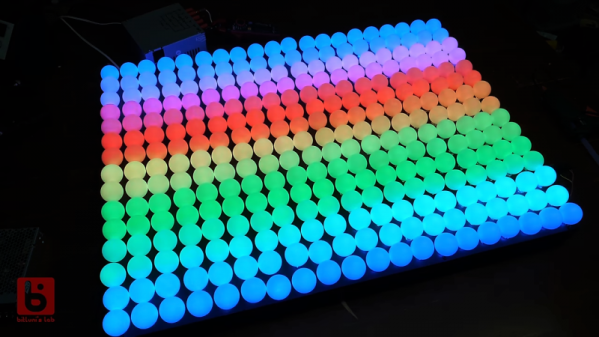
The idea [Leo] had a few years back was pretty smart. He noticed that there was no middle ground between cheap, pre-made LED signs and expensive programmable signboards, so he sought to fill the gap. The result was an ingenious “LED pin”, a tiny module with an RGB LED and a microcontroller along with a small number of support components. The big idea is that each pin would store its own part of a display-wide animation in flash memory. Each pin has two terminals that connect to metal cladding on either side of the board they attach to. These two conductors supply not only power but synchronization for all the pins with a low-frequency square wave. [Leo]’s method for programming the animations — using a light sensor on each pin to receive signals from a video projector — is perhaps even more ingenious than the pins themselves.

[Leo]’s idea seemed destined for greatness, but alas, the cruel realities of scaling up struck hard. Each prototype pin had a low part count, but to be manufactured economically, the entire BOM would have to be reduced to almost nothing. That means an ASIC, but the time and expense involved in tooling up for that were too much to bear. [Leo] has nothing good to say about the patent game, either, which his business partners in this venture insisted on playing. There’s plenty of detail in the video, but he sums it up with a pithy proclamation: “Patents suck.”

Watching this video, it’s hard not to feel sorry for [Leo] for all the time he spent getting the tech right only to have no feasible way to get a return on that investment. It’s a sobering tale for those of us who fancy ourselves to be inventors, and a cautionary tale about the perils of participating in a patent system that clearly operates for the benefit of the corporations rather than the solo inventor. It’s not impossible to win at this game, as our own [Bob Baddeley] shows us, but it is easy to fail.

Continue reading “Fail Of The Week: Bright Idea For LED Signs Goes Bad”

Adding RGB To A CRT

There was a time when all TVs came with only an antenna socket on their backs, and bringing any form of video input to them meant dicing with live-chassis power supplies. Then sets with switch-mode supplies made delving into a CRT TV much safer, and we could bodge in composite video and even RGB sockets by tapping into their circuitry. For Europeans the arrival of the SCART socket gave us ready-made connectivity, but in the rest of the world there was still a need to break out the soldering iron for an RGB input. [Jacques Gagnon] is in Canada, and has treated us to a bit of old-school TV input hacking as he put an RGB socket on his JVC CRT set.

Earlier hacks had inventive incursions into discrete analogue circuitry, but on later sets such as this one the trick was to take advantage of the on-screen-display features. The signal processing chip would usually have an RGB input with a blanking input to turn of the picture during the OSD chip’s output. These could be readily hijacked to provide an RGB input, and this is the course taken here. We see a VGA socket on the rear panel going to a resistor network on a piece of protoboard stuck in a vacant space on the PCB, from which a set of lines then go to the signal processing chip. The result is a CRT gaming monitor for retro consoles, of the highest quality.

For those of us who cut our teeth on CRT TVs it’s always good to see a bit of TV hacking. It’s a mod we’ve seen before, too.

This RGB Tree Has Its Roots In A PCB

[Paczkaexpress]’s RGB tree is a mix of clever building techniques and artistic form that come together into quite a beautiful sculpture.

The branches of his tree are made from strands of enameled copper wire capped with an RGB LED and terminated in a female header. The separate wires are all wound and sculpted into the form of a tree. The wire is covered in a very thin layer of plastic, which we highly recommend observing under a microscope, that allow it to maintain a uniform and reflective copper color without shorting, adding to the effect.

The part we found an especially pleasing mix of form and function was how the “roots” of the tree clicked home in the PCB base. The PCB holds the STM32, power components, and an LED Driver. It doesn’t hide how the magic works, and the tree really does get its nutrients from the soil it’s planted in. This would be a fun kit to build. Very clever and you can see the final effect after the break.

Continue reading “This RGB Tree Has Its Roots In A PCB”

A Farewell To YouTube Sub Counters Set To Break With API Change

Of all the things you never would have guessed you’d need just ten years ago, a YouTube subscriber counter would probably rank highly. You would have guessed that the little hits of dopamine accompanying each tick upward of a number would be so addictive?

As it turns out, lots of people wanted to keep a running total of their online fans, and a bewilderingly varied ecosystem of subscriber counters has cropped up. All of them rely on the API that YouTube exposes for such purposes, which as [Brian Lough] points out is about to change and break every subscription counter ever made. In the YouTube sub counter space, [Brian] is both an enabler – he built an Arduino wrapper to fetch YT sub counts easily – and a serial builder of displays for other YouTubers. The video below shows a collection of his work, many based on RGB LED matrix display, like the one used in his Tetris-themed sub counter. They’re all well-built, nice to look at, and sadly, destined for obsolescence sometime in August when the API changes.

The details of the API changes were made public in April, and for the subs count it amounts to rounding the count and displaying large counts as, for instance, 510k as opposed to 510,023. We’re confident that [Brian] and other display builders will be able to salvage some of their counters with code changes, but others will probably require hardware changes. Thanks, YouTube.

Continue reading “A Farewell To YouTube Sub Counters Set To Break With API Change”

Unique Clock Keeps Time The Fibonacci Way

You say your binary clock no longer has the obfuscation level needed to earn the proper nerd street cred? Feel like you need something a little more mathematically challenging to make sure only the cool kids can tell the time? Then this Fibonacci clock might be just the thing to build.

Granted, [TecnoProfesor]’s clock is a somewhat simplified version of an earlier version that was nigh impossible to decode. But with its color coding and [Piet Mondrian]-esque grids, it’s still satisfyingly difficult to get the time from a quick glance. The area of the blocks represents the Fibonacci sequence 1, 1, 2, 3, 5, and adding up which blocks are illuminated by the RGB LEDs behind the frosted front panel. That lets you tally up to 12 intervals; for the minutes and seconds, there are indicators for the powers multiples of 12 up to 48. Put it all together and you’ve got a unique and attractive graphical time display that’s sure to start interesting conversations when the mathematically disinclined try to use it. Check out the video below as the clock goes from 12:28:01 to 12:28:46. We think.

If this doesn’t scratch your itch for obfuscated clocks, we’ve got plenty of them. From random four-letter words to an analog digital clock to an epic epoch clock, we’ve got them all.

Continue reading “Unique Clock Keeps Time The Fibonacci Way”

A Ping Pong Ball LED Video Wall

Constrained builds are often the most fun. Throw an artificial limit into the mix, like time limiting your effort or restricting yourself to what’s on hand, and there’s no telling what will happen.

[bitluni] actually chose both of those constraints for this ping pong ball LED video display, and the results are pretty cool, even if the journey was a little rough. It seems like using sheet steel for the support of his 15 x 20 Neopixel display was a mistake, at least in hindsight. A CNC router would probably have made the job of drilling 300 holes quite a bit easier, but when all you have is a hand drill and a time limit, you soldier on. Six strings of Neopixels fill the holes, a largish power supply provides the 18 or so amps needed, and an Arduino knock-off controls the display. The ping pong ball diffusers are a nice touch, even if punching holes in them cost [bitluni] a soldering iron tip or two. The display is shown in action in the video below, mostly with scrolling text. If we may make a modest suggestion, a game of Pong on a ping pong ball display might be fun.

[bitluni] says that the display is on its way to Maker Faire Berlin this weekend, so stop by and say hi. Maybe he’ll have some of his other cool builds too, like his Sony Watchman Game Boy mashup, or the electric scooter of questionable legality.

Continue reading “A Ping Pong Ball LED Video Wall”

Twelve Channels Of LEDs Give RRRRGGGGBBBB Light

If you’ve ever searched Mouser or Digikey for LEDs parametrically, you won’t find just one red in your LEDs. You won’t find one green. There is quite literally an entire rainbow of colors of LEDs, and this rainbow goes into infrared and ultraviolet. You can search LEDs by frequency, and an RGEB LED is right at your fingertips. The ‘E’ stands for Emerald, and it’s better than a Bayer filter.

[ayjaym] over on Instructables realized anyone could buy a dozen frequencies of high-power LEDs, and the obvious application for this is to turn it into a tunable light source. The Angstrom is twelve LEDs, all different colors, and all controlled by PWM and piped down a single optical fiber. It’s an RRRRGGGGBBBB LED, ideal for microscopy, forensics, colorimetry, and seeing octoreen.

The heart of this device are twelve 3W star LEDs, with the following wavelengths: 390, 410, 440, 460, 500, 520, 560, 580, 590, 630, 660, and 780 nm. That’s deep red to almost ultra violet, and everything inbetween. These are powered by a 5 V, 60 W power supply, and controlled via a Raspberry Pi with 12 PWM channels in a circuit that’s basically just a bunch of MOSFETs. Proper heatsinking is required.

The impressive part of this build is the optics. A 3D printed mount holds and connects optical fibers and sends them into an optical combiner that is basically just a square acrylic rod. This is output to another optical fiber that will shine on just about anything. A webpage running on a Raspberry Pi sets the PWM channels of all the LEDs, and the resulting output shows up at the end of an optical fiber. It’s great if you want to look at something in a specific frequency of light. It also looks really cool, so that’s a bonus.