If you’ve got a mechatronic project in mind, a 3D printer can be a big help. Gears, levers, adapters, enclosures — if you can dream it up, a 3D printer can probably churn out a useful part for you. But what about more complicated parts, like sensors and user-input devices? Surely you’ll always be stuck buying stuff like that from a commercial supplier. Right?
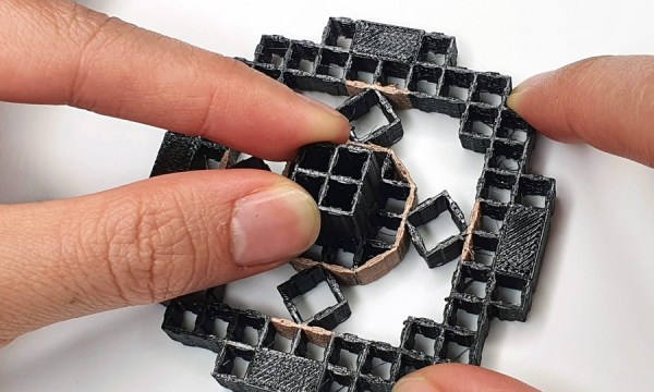
Maybe not, if a new 3D-printed metamaterial method out of MIT gets any traction. The project is called “MetaSense” and seeks to make 3D-printed compliant structures that have built-in elements to sense their deformation. According to [Cedric Honnet], MetaSense structures are based on a grid of shear cells, printed from flexible filament. Some of the shear cells are simply structural, but some have opposing walls printed from a conductive filament material. These form a capacitor whose value changes as the distance between the plates and their orientation to each other change when the structure is deformed.
The video below shows some simple examples of monolithic MetaSense structures, like switches, accelerometers, and even a complete joystick, all printed with a multimaterial printer. Designing these structures is made easier by software that the MetaSense team developed which models the deformation of a structure and automatically selects the best location for conductive cells to be added. The full documentation for the project has some interesting future directions, including monolithic printed actuators.
Continue reading “3D-Printing Complex Sensors And Controls With Metamaterials”