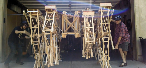
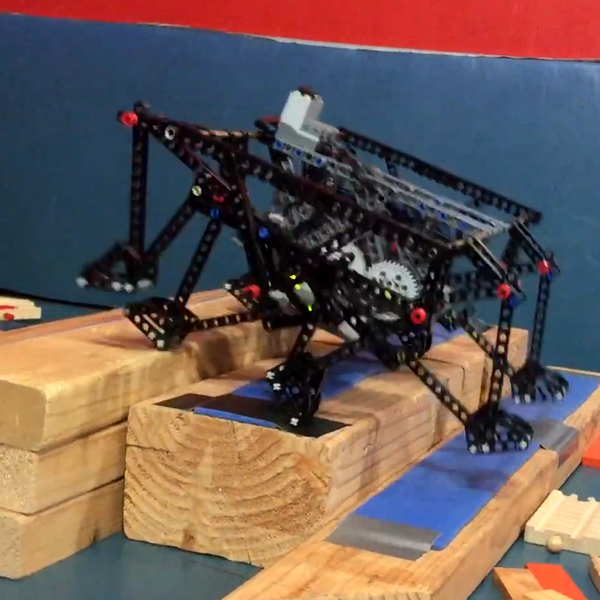
Father-and-son team [Wade] and [Ben Vagle] have developed and extensively tested two great walker designs: TrotBot and the brand-new Strider. But that’s not enough: their website details all of their hard-earned practical experience in simulating and building these critters, on scales ranging from LEGO-Technic to garage-filling (YouTube, embedded below). Their Walker ABC’s page alone is full of tremendously deep insight into the problem, and is a must-read.
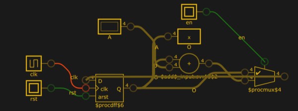
 These mechanisms were designed to be simpler than the Jansen linkage and smoother than the Klann. In particular, when they’re not taking a stroll down a beach, walker feet often need to clear obstacles, and the [Vagles’] designs lift the toes higher than other designs while also keeping the center of gravity moving at a constant rate and not requiring the feet to slip or slam into the ground. They do some clever things like adding toes to the bots to even out their gaits, and even provide a simulator in Python and in Scratch that’ll help you improve your own designs.
If you wanted a robot that simply moved, you’d use wheels. We like walkers because they look amazing. When we wrote [Wade] saying that one of Trotbot’s gaits looked animal-like, he pointed out that TrotBot got its working name from a horse-style gait (YouTube). Compared to TrotBot, the Strider family don’t have as much personality, but they run smoother, faster, and stronger. There’s already a 3D-printing-friendly TrotBot model out there. Who’s going to work something up for Strider?
How much do we love mechanical walkers? Enough to post about bicycles made with Jansen linkages, remote-controlled toy Strandbeests both with weaponry and without, power-drill-powered walking scooters, and of course basically anything that Theo Jansen is up to.
If a trip to [Wade] and [Ben]’s website doesn’t get you working on a walker project, physical or virtual, we don’t know what will.
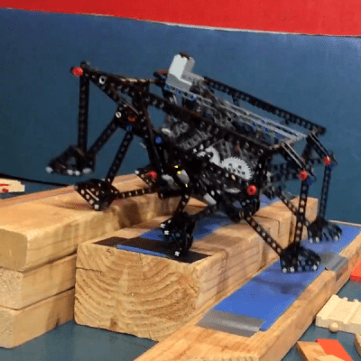
(And from the editorial department of deconfusion: the image in the banner is TrotBot, but it was just too cool to not use.)
Continue reading “Move Over Strandbeest, Here’s Strider!” →