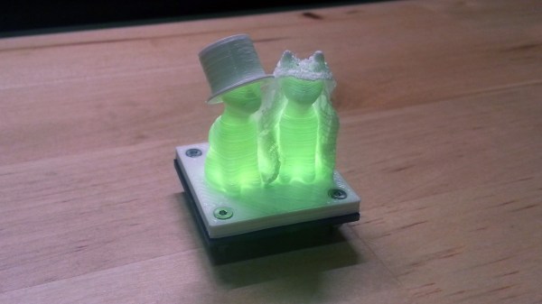
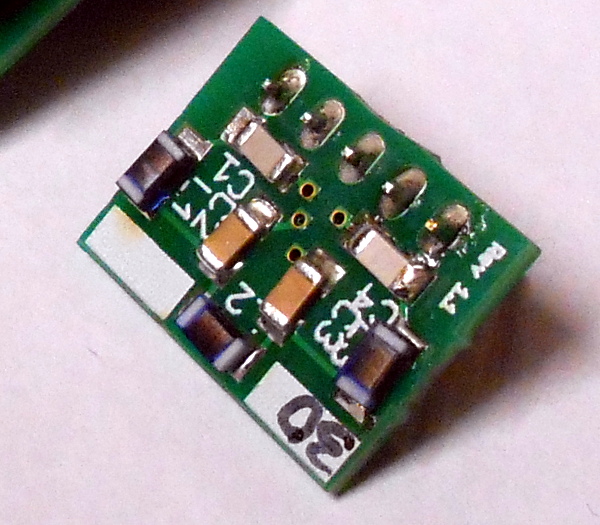
[ANTALIFE] is going to tie the knot sometime in 2017. Instead of sending out paper announcements or just updating his Facebook status, he wanted to give their family members something lasting and memorable, like a small trinket with a pair of light-up cats.
This project is pretty simple in theory. A pair of RGB LEDs cycle through the colors of the rainbow with the help of an ATtiny25 and resistors carefully chosen for each LED. But there are several challenges at play here. [ANTALIFE] wanted to design something quite small that would last at least a day on a single CR2032 coin cell. This project was his first foray into SMD/SMT design and construction. We think that this warrants its own congratulations, especially since it looks as though he made at least a dozen of these things.
[ANTALIFE] made things much easier for himself with the purchase of a cheap hot air rework station and used a chip clip to program the ‘tiny. The cats are a design from Thingiverse, which he modified to turn them into bride and groom. Watch a whole line of them glow after the break. We sincerely hope that a larger version of these cats end up on top of the wedding cake.
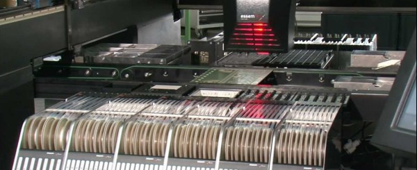
Recently we started a series on the components used to assemble a circuit board. The first issue was on dispensing solder paste. Moving down the assembly line, with the paste already on the board, the next step is getting the components onto the PCB. We’re just going to address SMT components in this issue, because the through hole assembly doesn’t take place until after the SMT components have gone through the process to affix them to the board.
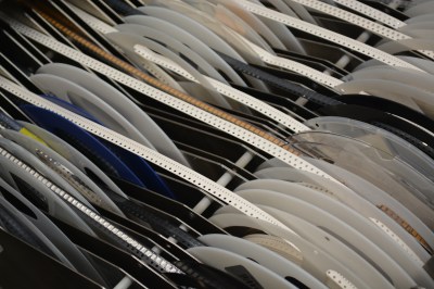
Reels!
SMT components will come in reels. These reels are paper or plastic with a clear plastic strip on top, and a reel typically has a few thousand components on it. Economies of scale really kick in with reels, especially passives. If you order SMT resistors in quantities of 1-10, they’re usually $.10 each. If you order a reel of 5000, it’s usually about $5 for the reel. It is cheaper to purchase a reel of 10 kOhm 0603 resistors and never have to order them again in your life than it is to order a few at a time. Plus the reel can be used on many pick-and-place machines, but the cut tape is often too short to use in automated processes.
If you are lucky enough to encounter a piece of homebrew electronics from the 1950s, the chances are that under the covers the components will be assembled on solder tags, each component with long leads, and chassis-mounted sockets for tubes. Easy to assemble with the most agricultural of soldering irons.
Open up a home build from the 1960s or early 1970s, and you might find the same passive components alongside germanium transistors mounted through holes in a curious widely spaced stripboard or even a home-made PCB with chunky wide tracks.
Solder tags aplenty in a commercial transmitter from the early 1960s
Cutting-edge 1970s homebrew
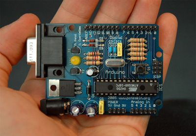
By the late 1970s and early 1980s you would find a more familiar sight. Dual-in-line ICs through-hole on 0.1″ spaced stripboard, and home-made PCBs starting to appear on fibreglass board. Easy to use, easy to solder. Familiar. Safe. Exactly what you’ll see on your breadboard nearly forty years later, and still what you’ll see from a lot of kit manufacturers.
But we all know that progress in the world of electronic components has not stood still. Surface-mount components have a history going back to the 1960s, and started to appear in consumer equipment from the end of the 1980s. More components per square inch, smaller, cheaper devices. Nowadays they are ubiquitous, and increasingly these new components are not offered in through-hole versions. Not a problem if your experiments are limited to the 741 and the 555, but something that rather cramps your style if your tastes extend to novel sensors for a microcontroller, or RF work.
This development has elicited a range of reactions. Many people have embraced the newer medium with pleasure, and the Hackaday.io project pages are full of really clever SMD projects as a result. But a significant number have not been able to make the jump to SMD, maybe they are put off by the smaller size of SMD components, the special tools they might require, or even the new skills they’d have to learn. When you sell a kit with SMD components these are the reactions you will hear from people who like the kit but wish it was available in through-hole, so this article is for them. To demystify working with SMDs, and to demonstrate that SMD work should be within the grasp of almost anyone who can wield a soldering iron.
But They’re So Tiny!
Tiny SMDs – fortunately most of which you will not have to worry about.
It’s likely to be the first reaction from a lifelong through-hole solderer. SMD parts are often very small indeed, and even those with larger packages can have leads that seem as numerous and thin as the hairs on a cat when seen with the rabbit-in-the-headlights panic of the uninitiated.
But it is important to take a step back and understand that not all SMDs are created equal. Some of them are grain-of-sand tiny and only hand-solderable by those with God-like powers, but plenty of devices are available in SMD packages large enough for mere mortals.
So don’t worry when you look at a board covered with grain-of-dust-sized components. Very few people could attempt that level of construction, your scribe certainly can’t. (We await commenters claiming to routinely hand-solder thousand-pin BGAs and 01005 chip components with anticipation, however such claims are useless without proof.)
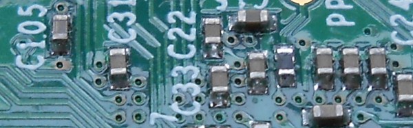
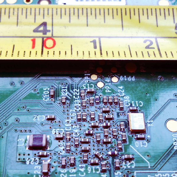
Instead, concentrate on the SMD packages you can handle. SMD chip component packages are refered to by a number that relates to their dimension. Confusingly there are both metric and imperial versions of the scheme, but the format is the same: length followed by width.
Consider the picture above with the PCB and the tape measure, it’s the underside of a Raspberry Pi model B+, and will have been assembled by a robotic pick-and-place machine. The majority of the components are very tiny indeed, but you will notice L3 as the black component towards the bottom left that looks huge compared to its neighbours. That package is a “1008”, 0.1 inches long by 0.08 inches wide. It’s still tiny, but imagine picking it up with a pair of tweezers under a magnifying glass. Not so bad, is it. You’ve probably handled plenty of things in that size range before, do SMD parts seem so scary now? The larger components – 0805, 1008, and 1206 – are surprisingly within the grasp of the average maker.
But I need all sorts of special tools!
Retro Populator, a homebrew pick-and-place machine we featured back in 2014
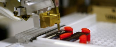
In a commercial environment an SMD device will be assembled by machine. Glue or solder paste will be printed in the relevant parts of the board, and a robotic pick-and-place machine will retrieve components from their tape packaging and automatically place them in their correct orientations. The board will then be soldered all-at once, either in a reflow oven or by a wave soldering machine.
You’ll also see all manner of commercial kit aimed at the bench-top SMD constructor. Hot air soldering stations or SMD bits for conventional irons, all of which are very useful but come with a hefty price tag.
The good news is that you don’t need any of these special tools to dip your toe into the SMD water. You almost certainly already have everything you need, and if you don’t then very little of what you lack is specifically for SMD work. If you have the following items then you are good to go:
A basic SMD soldering toolkit
A good light source. Even the larger SMDs are still pretty small. Plenty of light ensures you will be able to see them clearly. A good downward pointing desk lamp should suffice. A clear high-contrast surface. Because SMDs can be difficult to see, it helps if they are manipulated over a bright white surface. A fresh sheet of white printer paper on a desk makes a suitable working area. Good hands-free magnification. Unless you are fortunate enough to have amazing eyesight, you will need a decent magnifier to work with surface-mount components. The “Helping hands” type on a stand are suitable. A very small flat-blade screwdriver. You will need this to hold surface-mount components down while you solder them. A good-quality set of precision metal tweezers. You will need these for picking up, manipulating, and turning over surface-mount devices. A fine-tipped soldering iron. If you have a standard fine tipped iron suitable for use with conventional 0.1” pitch through-hole components then you should be well-equipped.
That said there is one special tool that might be worth your consideration. Holding an SMD device while soldering it can sometimes seem like a task that needs three hands, so one or two tools can be found to help. Fortunately this is something you can build yourself. Take a look at the SMD Beak, a weighted arm for example, or your scribe’s spring clamp third hand.
I’m sorry, this is just beyond my soldering skill level
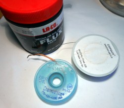
Desolder braid and plenty of flux are your friends.
It is easy to imagine when you are looking at an SMD integrated circuit that its pins are just too small and too close together, you couldn’t possibly solder them by hand. The answer is that of course you can, you simply need to view how you solder them in a different way.
With a through-hole IC you solder each 0.1″ pitch pin individually. It is something of a disaster if you manage to put a solder bridge between two pins, and you race for your desolder pump or braid.
With a surface-mount IC by comparison there is little chance that you as a mere mortal could solder each pin individually, so you don’t even try. Instead you solder an entire row at once with an excess of solder, and remove the resulting huge solder bridge with desolder braid to leave a very tidy and professional-looking job. Surface tension and plenty of flux are your friends, and there is very little soldering skill required that you do not already have if you are an experienced through-hole solderer.
If you can hold it down onto the board and see it clearly with your magnifier if necessary, then it doesn’t matter what the component is, you can solder it. Give it a try, you’ll surprise yourself!
What next?
1206 chip discrete components hand-soldered to a PCB
So we hope we’ve convinced you as an SMD doubter, that you have the ability to work with SMDs yourself. What next?
But there is no substitute for practice. Find a scrap board populated with reasonably-sized surface-mount components, and have a go at reworking it. Desoldering its components may be a bit difficult, but you should easily be able to rework the solder joints. Slather an integrated circuit’s pins with flux, and try running a blob of molten solder along them, then removing the excess with desolder braid. The great thing about a scrap board is that it doesn’t matter if you damage it, so you can practice these techniques to your heart’s content until you are satisfied with your new-found skill.
So you’re ready to move forward, and make your first SMD project. Well done! What you do next is up to you. Design your own circuit and get a PCB made, buy a kit, or find an SMD project you like on Hackaday.io with downloadable PCB files and order your own.
Whatever you do, be happy that you’ve conquered your SMD fears, and resolve to be first in the queue to try any new technology in the future!
The general process of circuit board assembly goes like this: You order your PCBs. You also order your components. For surface mount components, you apply solder paste to the pads, put the components on top, and then heat the board up so the solder paste flows and makes a bond. Then for through hole components you put the leads through the holes, and solder them with an iron or a solder wave or dip. Then you do an inspection for defects, program any microcontrollers, and finally test the completed board to make sure everything runs.
The tricky part is in volumes. If you’re only doing a few boards, it’s usually easiest to assemble them by hand. In the thousands you usually outsource. But new tools, and cheap hacked tools, have made it easier to automate small batches, and scale up into the thousands before outsourcing assembly.
In this new series which we’re calling Tools of the Trade we’ll be covering a variety of tools used for building products, and we’re starting with circuit board assembly. Let’s investigate our tools of the trade: solder paste dispensing. Continue reading “Tools Of The Trade – Solder Paste Dispensing”→
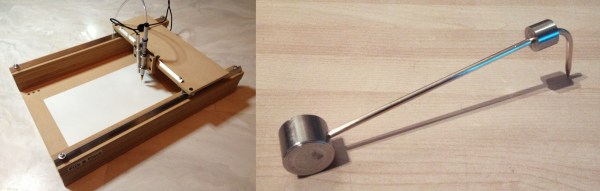
Populating a board with tiny SMT parts can be really tricky, and we’ll take all the help we can get. If you’re in the same boat, [vpapanik] has two devices you should check out.
First up is the manual pick-and-place machine. Wait, what? A manual pick-and-place? It’s essentially an un-driven 2-axis machine with a suction tip and USB inspection microscope on the stage. The picker apparatus is the “standard” needle-plus-aquarium-pump design, and the rails are made from angle aluminum and skateboard bearings.
Yeah, yeah, yeah. It’s not a robot. But sometimes the right jig or tool makes all the difference between a manual procedure being fiddly and being graceful. And we couldn’t help but laugh at the part in the video where he demonstrates the “machine” moving in a circular pattern.
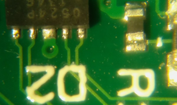
Fortunately (or unfortunately), [ucDude] has had the opportunity to try out a high quality video microscope while soldering some small surface mount components. He loved it, the problem was he had a hard time going back to using just his eyes. He wanted a video microscope but the cost for a professional one could not be justified. The solution? Build one!
[ucDude] called on one of his photographer friends to help. After discussing the project they decided to use a webcam and a lens from an SLR camera. Testing with the webcam resulted in an image that could not be zoomed-in enough, plus having to connect it to an external computer proved to be a bulky solution. They next tried a Raspberry Pi, camera module and zoom monocular. It worked great! The entire assembly was then mounted to a camera boom stand making it easy for the camera to be positioned over the work area and out of the way of hands and soldering irons. The Raspberry Pi’s HDMI output is plugged straight into an HD monitor. The result is exactly what [ucDude] was looking for. Now he can quickly and confidently solder his surface mount circuit boards.
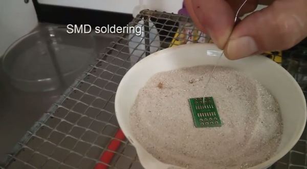
Need to do some SMD soldering? No tools? No problem! Here’s a creative method that could be a handy tool to add to your belt: SMD soldering using hot sand.
[Oliver Krohn] recently released this little video demonstrating how to perform re-flow soldering using hot sand. He’s using a bunsen burner to heat up a ceramic pot of sand to use as a kind of hot plate. It seems to work pretty well, and it’s a very unique way of doing it — if you wanted to get a bit more technical, you could also throw a temperature probe in the sand to get a much finer heat control!